Friday, 31 July 2020

LG26LC2R, LG32LC2R LCD TVs Service adjustments, Software program and EDID data download-install procedure in detail

FACTORY MODEL: 26LC2R-TJ / 32LC2R-TJ - CHASSIS : LP61C

All of the26 - 32" LCD TV, LP61A/C, LN61A chassis (HURRICANE 3 MIDDLE) by manufacturing LG TV Plant all over the world.

 Because this is not a hot chassis, it is not necessary to use an isolation transformer. However, the use of isolation transformer will help protect test instrument.

Adjustment must be done in the correct order.
The adjustment must be performed in the circumstance of 25±5°C of temperature and 65±10% of relative humidity if there is no specific designation.
The input voltage of the receiver must keep 100~220V, 50/60Hz.
Before adjustment, execute Heat-Run for 30 minutes at RF no signal.

Adjustment items
3.1 PCB assembly adjustment items
• Download the VCTP main software (IC601,VCPT)
• Channel memory (IC603,EEPROM)
• Colorcarrier Adjustment
3.2 SET assembly adjustment items
• DDC Data input.
• Adjustment of White Balance.
• Factoring Option Data input.
4. PCB assembly adjustment
4.1 PCB assembly adjustment method
(Using VCTP Download program)
4.1.1.Download program installation
(1) Extract a Zip file.

(2) Visual I2C & LPT Driver Installation.

Install the LPT Driver
Install the Visual I2C

LPT Port Driver (LptDrv) Setups : Program Files > Micronas >Visual I2C > Port_Driver
*Use for Windows 95/98 : Setup_LptDrv_v0104_9x.exe
*Use for Windows 2000/XP : Setup_LptDrv_v0202_XP_2000.exe
*Use for Windows NT : Setup_LptDrv_v0104_NT.exe
(3) Verification (Start > Programs > Micronas > Visual I2C or LptDrv)

(4) LPT delay setting (File > Preference > LPT preferences)

(5) Exchange the bootloader.bat file.

Double click the Box area.

=> Select the "Bootloader.bat" file(install >VCTP_download > Bootloader) => Push "OK"

=> Finish the program, after saving the file "download_cs.vi2c"
(if you click , the massage appears automatically)

Software program download
• Preliminary steps
4.1.2.1 Download method 1 (PCB Ass’y)

Connect the download jig to D-sub jack
(2) Execute ‘Download.vi2c’ program in PC, then a main window will be opened.

(3) Double click the blue box and confirm "Bootloader Version" as 40.

(4) Click the "Erase Flash" button.

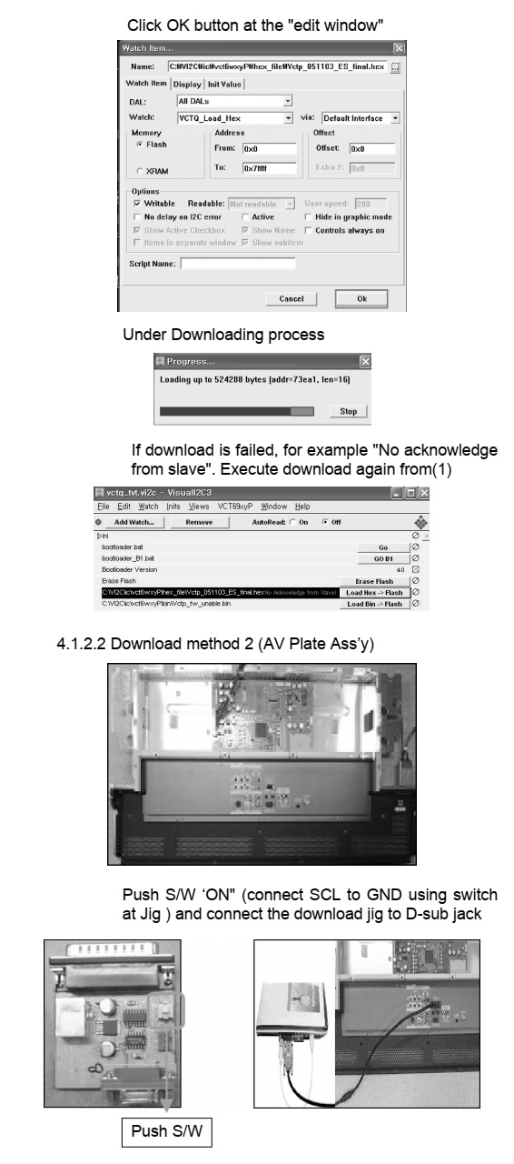
(5) Double click the download file low, then "edit" window will be opened,

(6) Click the choice button in the "edit window", then "file choice window" will be opened.

(7) Choose the Hex file in folder and execute downloading with click " open" button.

(8) Click OK button at the "edit window"

(9) Under downloading process.

(10) If download is failed, for example "No acknowledge from slave". Execute download again from (1)

4.1.2.2 Download method 2 (AV Plate Ass’y)

(1) Push S/W ‘ON" (connect SCL to GND using switch at Jig ) and connect the download jig to D-sub jack.

(2) Supply the power (Stand-by 5V) and wait for 3 seconds.

(3) Push the S/W off (Disconnect SCL to GND using switch at jig)

(4) Execute ‘Download.vi2c’ program in PC, then a main widow will be opened.

(5) Double click the blue box and confirm "Bootloader Version" as 40.

(6) Click the "Erase Flash" button.

(7) Double click the download file low then, "edit" window will be opened.

(8) Chick the choice button I n the "edit window", then "file choice window’ will be opened.

(9) Choose the Hex file in folder and execute downloading with click "open button"

(10) Click OK button at the "edit window"

(11) Under downloading progress.

(12) If download is failed, for example "No acknowledge from slave", execute download again from (1)

4.1.2.2 Download method 3 (SET)
(1) Push the "Tilt" button in an Adjust Remocon Then the LCD TV will change a "slave mode"

(2) Connect Zig to TV using a D-sub cable.

(3) Execute ‘Download_CS.vi2c’ program in PC, then a main widow will be opened.

(4) Click "GO" button.

If you don’t push the "go” the Hex file would not be downloaded although the download proceeds normally at first glance.

(5) Double click the blue box and confirm "Bootloader Version" as 40.

(6) Click the "Erase Flash" button.

(7) Double click the download file low then, "edit" window will be opened.

(8) Chick the choice button I n the "edit window", then "file choice window’ will be opened.

(9) Choose the Hex file in folder and execute downloading with click "open button"

(10) Click OK button at the "edit window"

(11) Under downloading progress.

(12) If download is failed, for example "No acknowledge from slave", execute download again from (1)

4.1.2. S/W program download
(1) Connect the download jig to D-sub jack
(2) Execute ‘Channal.vi2c’ program in PC, then a main widow will be opened.

(3) Push the button change and select the Channel memory data.

(4) Check the communication is OK or not.
=> Push the Read area (Ackn. Check) and check Cyan area is OK message.

(5) Push the Update NVM from File.

4.1.3. Color carrier Adjustment (inspection process)
a. Tuning the RF signal
ZJ, TJ, CJ : PAL Philips Pattern (with Color Bar)
MJ : NTSC Digital Pattern (with Color Bar)

b. push the "adj" key in the adjustment remocon.

Adjust remote control [Service remote control]

4.2 SET assembly adjustment method
*Caution :
Each PCB assembly must be checked by check JIG set.(Because power PCB Assembly damages to LCD Module, especially be careful)
4.2.1 EDID(The Extended Display Identification Data ) / DDC(Display Data Channel) download
(1) Extract a Zip file
* Caution
- Use the proper signal cable for EDID Download
* Caution: - Never connect HDMI & D-SUB Cable at the same time.
- Use the proper cables below for EDID Writing.

EDID data

e.Checksum: Changeable by total EDID data

4.3 Adjustment of White Balance
* In case of White Balance rework, you have to RESET the previous White Balance data.
(You can do that by pushing the "IN-START" key in adjust remocon and reset)
4.3.1 Required Equipment
• Remote controller for adjustment
• Color Analyzer (CA-110 or CA-210 or same product; ch : 9)
• Auto W/B adjustment instrument (only for Auto adjustment)
• AV Pattern Generator
ZJ, TJ, CJ – model : 202 (PAL-BDGHI), pattern:78 (216 Gray)
MJ – model : 207 (NTSC-J), pattern : 78 (216 Gray)

4.3.2 Connecting diagram of equipment for measuring (For Automatic Adjustment)
[Push the "POWER ON" key at the Adjust Remocon before Adjustment of W/B, the Baud rate & PSM, CSM will change 115200bps, Standard (MJ: Optimum), Normal]

4.3.3 Adjustment of White Balance for Manual adjustment
• Operate the zero-calibration of the CA-110 or CA-210, then stick sensor to LCD module when you adjust.
• For manual adjustment, it is also possible by the following sequence
1) Select RF no signal by pressing "POWER ON" key on remote control for adjustment then operate heat run more than 15 minutes.
2) As below Fig. 7, Supply 216Level (85 IRE) Gray pattern to Video input.
26/32LC2R-ZJ : AV3 or AV4(Input 50Hz)
26/32LC2R-TJ : AV1or AV2(Input 50Hz),
26/32/37LC2R-CJ : AV1 or AV2 (Input 50Hz)
26,32LC2R-MJ : VIDEO1 or VIDEO2 (Input 60Hz)
3) Press the POWER ON KEY on R/C for converting input mode.
4) Enter the White Balance adjustment mode by pressing the
IN-START key (White Balance) on R/C.
5) Stick sensor to center of the screen and select each items (Red/Green/Blue Gain and Offset) using / (CH +/-) key on R/C..
6) Adjust Only High Light with R Gain / B Gain using / (VOL + / -) key on R/C.
7) Adjust it until color coordination becomes as below.
(Initially, R/G/B gain and R/G/B offset values are fixed as below)
Red Gain : 80 , Green Gain : 80 , Blue Gain : 80
Red Offset : 80, Green Offset : 80 , Blue Offset : 80
* Target Value [PSM: Standard(ZJ, TJ, CJ), Optimum(MJ),CSM: Normal]
-Normal (9300K) x ; 0.283±0.003 y ; 0.298±0.003
=> Reference Value(Automatically fixed)
-Cool(11000K): x:0.274±0.003, y: 0.286±0.003
-Warm(7200K) : x:0.303±0.003, y: 0.319±0.003

8) When adjustment is completed, Exit adjustment mode using EXIT key on R/C.


Tuesday, 21 July 2020

LG split air conditioners fault codes and details – repair help

Fault Codes Universal Split LG Air Conditioning fault codes and details

If there is a fault on any LG Universal unit, a two digit number will appear on the remote controllers led display. If the unit does not have a remote controller the fault will be displayed using the LED's on the front of
the indoor unit.

The “Units” digit of the fault code is shown by the power led which has the following symbol by it
This is usually Red, but on a few models it is Green.

The “Tens” digit will be displayed by one other led, usually the “Sleep” or “Filter” lamp.

· The function provides self-diagnosis and displays an error code if there is any trouble.
· Error codes are displayed on the Indoor unit’s Wired Remote as CH**, and/or Fascia Display. In addition, the code is indicated via LED’s on the outdoor unit control board.
· If more than two troubles occur simultaneously, the lower number of error code is displayed first.
· After an error occurs, if error is released, error LED is also released simultaneously.

Indoor and outdoor unit fault codes

Fault code-1

Is a fault with the Indoor unit return air Thermistor
Unplug the Thermistor from the PCB and Check its resistance check against this graph. 

Alternatively the sensor can be tested while still connected to the PCB measure the DC voltage across the resistor and check it against the graph below

Fault Code 03

Indicates a wiring error between the remote controller and the fan coil, this is most common in group control applications where more than 1 fan coil is connected to a single remote controller.
Firstly check the wiring has been done correctly see below.  Next check the switch in the back of the remote controller, it has to be set to Group or GR1 for group control, the Factory setting is Single or SG, after setting the switch reset the power for 2 minutes. If the fault does not clear, check the Voltage of the remote controller cable.

Fault Code 04
Fault code CH04 indicates that the float switch of the fan coil has raised.
On fan coils without a drain pump it indicates that the jumper (blue plug with 30mm of blue wire) in terminal CN FLOAT is missing.
If the fan coil is running and the float rises it will take 3 ½ minutes for the fault to show on the controller, this is to give the unit time to pump excess water away. Once the float falls, (or the jumper is put back into the board) it will not be possible to clear the fault for 40 seconds. It is considered good practice to reset the power to clear this fault code.

Fault Code 05
These error codes indicate a communication fault between the indoor and outdoor units; it appears approximately 5 minutes after powering up the system.
The communication between the units is a fluctuating DC voltage commonly called a serial signal, it can be easily lost if the wiring is not done correctly. If there is a communication error fault CH05 will appear on the
Wired Remote within 5 mins of powering up the system.
Testing
First check for any isolator or switches on the interconnecting cable and ensure both the Comms and Neutral are un-switched. Then confirm connections are correct and secure at both the Indoor and Outdoor units.
Check if any other devices are connected on the interconnecting cable, remove such equipment, and connect them elsewhere.
Open the outdoor unit to reveal the Main PCB and identify the Green and Red LED’s on that board. The Green LED should be lit steadily if power is present, the Red LED should be doing one of the following:-
1. If the outdoor unit receives communications from the indoor unit, the Red LED should be flickering.
2. If the Red LED glows steadily without flickering, then no communication is being received from the indoor unit. Check the interconnecting cables for any short or open circuits, not forgetting the connecting cables between the terminal rail and PCB on both Indoor & Outdoor units. Repair wiring, or replace the Indoor PCB as necessary.
3. If the Red LED does not light at all, then the fault is with the outdoor PCB, or connections to it. Confirm that the Outdoor PCB is receiving power (Green LED lit). Repair wiring, or replace the Outdoor PCB as necessary.
4. If Condition 3 above applies please check the following and repair/replace as required. Failure to do so may result in the new PCB becoming damaged.
a. Check PCB Control Fuse, if blown, identify cause and rectify.
b. Check Fan Motor(s).
i. AC Motors for Short Circuits or Down to Earth.
ii. BLDC Motors (See Product Technical Update - Sheet 83).
c. Reversing Valve Coil, for Short Circuit or Down to Earth.
d. Reactor, for Open Circuit.
e. Electronic Expansion Valve Down to Earth (See Product Technical Update - Sheet 96).
f. Compressor, for Short Circuit or Down to Earth.

Additional Tests
Set your meter to DC Volts, Test between terminals 2 and 3 of the outdoor unit and wiring terminals, you should see 0-75 Vdc, it will be fluctuating rapidly.
If this signal voltage is not present disconnect the wire from terminal 3 of the inter unit cabling, and test terminal 3 Voltage again. If Voltage is still not present, the outdoor PCB must be faulty.
If this signal voltage is detected leaving the outdoor unit, reconnect wire 3 and check what is being received at the indoor unit. Disconnect wire 3 from the indoor terminal block and check the DC Voltage between this wire and terminal 2. It should be the same as what you saw at the outdoor unit, if not your wiring is at fault.
With the wire still disconnected, check between terminals 2 & 3. You should see a relatively steady voltage in the range of 0.5 – 15Vdc (Negative). Any significant difference would indicate a faulty Indoor PCB.
Important: Comms Errors are also created on Universal “Synchro Systems” when they are not configured/commissioned correctly. Please follow the correct Synchro Commissioning Procedures.

Fault code 06
Is a problem with the Indoor unit coil outlet Thermistor
Unplug the Thermistor from the indoor PCB and Check its resistance against this graph. Alternatively the sensor can be tested while still connected to the PCB measure the DC voltage across the resistor and check it against the graph below

Fault Code 07
On Multi split systems, the first unit switched on is the cool heat master, the master tells the condensing unit what to do. If the condenser is in heating and any slave is set to cooling a CH07 fault code will appear.
Likewise if the condenser is in cooling and any slave is set to heating a CH07 fault code will appear. If the master is switched off the next longest running unit becomes the master.  To clear the fault turn off the unit at the remote controller, turn it back on again and change the mode.

Fault Code 09
Check for loose connections or dry joints where EEPROM connects on Main PCB, repair if possible, if not replace PCB.

Fault Code 10
Indoor Fan Motor problem.

Fault Code 21
This fault is caused by an over current in the inverters DC power circuit. If the DC part of the circuit exceeds 14 Amps fault code 21 will be displayed.
This is caused by either the inverter PCB being faulty or compressor being short circuit or down to earth.  Disconnect the electrical connections to the compressor and check the resistance of the compressor windings, measure from U to V, V to W and W to U the values should be between 0.25 and 5 Ohms each.  The next test is to measure the resistance of the compressor windings to earth.
Using a Megger (High Voltage Meter) measure the resistance from any of the 3 compressor terminals to an Earth point (pipe work).  The value should exceed 2 M Ohms.  If the compressors fail these tests it will need replacing.
If the compressor is OK you will need to check the inverter output voltages. Please see section on Inverter testing at end.

Fault Code 22
This fault is caused by a Compressor over-current.

Fault Code 23
This fault indicates a fault in the DC part of the inverter circuit; it means that the Dc Voltage to the inverter is below 140 V Dc, it should be 370 V for single phase machines and 600 V dc for three phase machines. The fault is usually caused by the inverter charging resistor being faulty; this component is mounted on the outdoor unit PCB and cannot be replaced.
Start the unit running and measure the DC Voltage supply to the inverter. This is easiest to measure at the inverter capacitors; it should be 370 V for single phase machines and 600 V dc for three phase machines.

Fault Code 24
If the unit has a low or high pressure fault CH24 will display.
If the LP switch goes open circuit the compressor will be stopped, on inverter units this can take up to 30 seconds. The LP Switch goes open circuit when the suction pressure falls below 0.5 bar the Hp Switch opens
at 41 bar.
The fault code will only occur if the pressure switch is tripped 5 times within 1 hour, this can only be reset by switching off the power to the condensing unit for 2 minutes.
If your unit does not have any pressure switches it may still have a plug on the outdoor unit PCB labelled CN Press, it should have a link plugged in, if the link is missing it must be replaced.
Fault Code 25
This fault indicates a problem with the incoming power supply to the system.
Measure the Voltage of the incoming supply, if it is less than 140V AC or greater than 300V AC this fault will occur.
If the Power supply is correct and the fault persists replace the outdoor unit PCB.

Fault Code 26
This fault indicates a problem with the positioning system of the inverter compressor, which indicates a seized compressor.
Firstly check the compressor is correctly connected. Next reset the power supply to the system ensuring the power is left off for 5 minutes. Start the unit up, after a couple of minutes the compressor will try and start, you
can hear a high pitched whine when it does. If the compressor does not start turning within a couple of seconds the whining will stop. The compressor will try to start 3 times then the fault will recur.
Fault Code 27
This fault indicates a problem with the inverter module, see section on testing inverters. Also check reactor is connected to the PCB and check its resistance it should be well under 1 Ohm.
Fault Code 28
This fault indicates a problem in the DC part of the inverter circuit; it means that the DC Voltage to the inverter is too high.
Start the unit running and measure the DC Voltage supply to the inverter. This is easiest to measure at the inverter capacitors; it should be 370 V for single phase machines and 600 V dc for three phase machines.

Fault Code 29
Check and correct for any:
1. Overload operation (Pipe restrictions / Restricted Airflow / EEV defect / Refrig. Overcharged)
2. Compressor damage (Insulation damage / Motor damage)
3. Input Voltage Low
4. ODU Inverter PCB assembly damage.

Fault Code 32
Indicates that the Inverter compressor discharge temperature is high (above 105ºC) this usually indicates the system has either a shortage of refrigerant or a blockage in the system.
Reset the power to the unit for 2 minutes and restart it. If the compressor starts measure the compressor discharge temperature, typically it should not be more than 50ºC above the ambient temperature around the
condensing unit. It may take quite a long period for the compressor to overheat so don’t just start the unit and run. Make sure you check the unit is operating correctly and providing adequate cooling.
Fault Code 33
Indicates that the fixed speed compressor discharge temperature is high (above 105ºC) this usually indicates the system has either a shortage of refrigerant or a blockage in the system.
Reset the power to the unit for 2 minutes and restart it, If the compressor starts measure the compressor discharge temperature, typically it should not be than 50ºC above the ambient temperature around the  condensing unit. It may take quite a long period for the compressor to overheat so don’t just start the unit and run. Make sure you check the unit is operating correctly and providing adequate cooling.
Fault Code 39
Check and repair or replace as necessary:
1. PCB defect / Wiring defect
2. Different Micom Software Version
3. ODU Inverter PCB assembly damage
Fault Code 40
This fault indicates a problem with the current drawn by the AC part of the inverter circuit.

Fault Code 41
This fault indicates an Inverter Compressor discharge Thermistor fault
Unplug the Thermistor and Check its resistance check against this graph:

Alternatively the sensor can be tested while still connected to the PCB measure the DC voltage across the resistor and check it against the graph below..

Fault Code 44
Indicates a fault with the Outdoor unit air Thermistor
Unplug the Thermistor from the PCB and Check its resistance check against this graph:  Alternatively the sensor can be tested while still connected to the PCB measure the DC voltage across the resistor and check it against the graph below.

Fault Code 45
Indicates a problem with the condenser coil outlet Thermistor
Unplug the Thermistor from the indoor PCB and Check its resistance against this graph:  Alternatively the sensor can be tested while still connected to the PCB measure the DC voltage across the resistor and check it against the graph below.

Fault Code 46
Indicates a problem with the compressor suction Thermistor
Unplug the Thermistor from the indoor PCB and Check its resistance against this graph:  Alternatively the sensor can be tested while still connected to the PCB measure the DC voltage across the resistor and check it against the graph below.

Fault Code 47
Indicates an Inverter Compressor discharge Thermistor fault
Unplug the Thermistor from the PCB and Check its resistance check against this graph:  Alternatively the sensor can be tested while still connected to the PCB measure the DC voltage across the
resistor and check it against the graph below.

Fault Code 48
This fault indicates that the compressor discharge sensor and the condenser air temperature sensors are both unplugged. Both these sensors are connected to a single connector on the outdoor unit PCB, plug it in and
the fault will go away.
Fault Code 51
This indicates that the capacity of the indoor unit / units is too great for the condensing unit. Make a note of the model number of the fan coil/coils and the condensing unit and check with the equipment supplier that the
units you have installed can be connected together.
Fault Code 52
This fault code indicates a communication error between the Main and Sub micom (CPU’s) on the outdoor unit main PCB. Check for evidence of damage, if none found reset power, if fault reappears replace PCB.
Fault Code 53, (see fault code 05)
Fault Code 54
This fault normally indicates a lost phase or the phases are reversed on the power supply to 3 phase units.
Check all 3 phases are available at the power terminals to the unit. You should have 415v AC across red to blue, blue to yellow and red to yellow,
If this is all ok turn off the power and swap the red and yellow cores of the power supply cable over, reset the power and the unit will operate.
Fault Code 60
Check the correct PCB assembly has been installed, check for dry joints, replace outdoor unit PCB if nothing is found.

Fault Code 61
Indicates the outdoor unit condenser coil temperature is high above 65ºC, this will usually be experienced in cooling mode and will indicate insufficient air being drawn over the coil.
Check there are no blockages to the coil (carrier bags dirt etc); check the air flow is not short circuiting from the front to the back of the unit and check for Nitrogen in the system.
Fault Code 62
Indicates the outdoor unit Inverter heat-sink thermistor has detected that the heat sink is overheating 85ºC.
This is usually caused by debris blocking the heat-sink fins or an error with the thermistor, see code 65.

Fault Code 65
Is a problem with the Inverter PCB heat sink thermistor for the heat sink on the outdoor unit PCB, unplug the Thermistor from the PCB and Check its resistance against this graph:  Alternatively the sensor can be tested while still connected to the PCB measure the DC voltage across the resistor and check it against the graph below.

Fault Code 67
This is a problem with the Outdoor Fan Motor, where rotation is not detected, and could be result of either Mechanical or Electrical failure.
· Check that motor is free to rotate and not seized.
· Check the motor is electrically sound, windings not Open or Short circuit.
· Check power output from PCB to fan motor.
· Check rotation feedback circuit.
More modern units use inverter fan motors, which are powered by a DC Voltage.
In reality these fan motors are AC fan motors with a small inverter-type circuit build inside. This inverter circuit is integrated with the fan motor and impossible to replace, you have to replace the entire fan motor.
Similar to inverter-controlled compressors, the speed of these fan motors can be changed to whatever is needed (within certain limits). In practice the change in fan speed is not ‘continuous’ but certain fixed speeds
have been programmed inside the AC unit.  This type of fan control can be recognized by the 5 wires coming from the fan on a connector with 7 possible connections.
These fan motors have 5 connections, power supply is 360VDC, and the speed is determined by a voltage ranging from 0 (0 rpm) to 5VDC (max speed) and a power supply for the internal electronics of 15VDC.
These motors are easy to identify from a wiring diagram, they always show them not connected to anything as the electronics are too difficult to draw on the diagram.
Detail of Hall Sensors.
A Hall effect sensor works like a magnetic reed switch, one end is wired to a 15 Vdc supply and the other is the feed back to the PCB. As a magnet mounted on the rotor of the motor passes the hall sensor the reed
switch closes momentarily and allows the DC signal to flow through it back to the PCB. The hall sensors have a resistance so the voltage fed back to the PCB will only be approximately 12V DC.
The PCB will know what speed the fan motor should be turning as it is also controlling the output of the inverter, if there is a discrepancy between the inverter output RPM and the feedback from the hall sensors a
fault will occur. Usually the fan will rev very fast for a few seconds then stop this indicates hall sensor problems.
Replace either Motor or Fan PCB as necessary.

Fault Code 73
Check and repair or replace as necessary:
1. Overload operation (Pipe restrictions / Restricted Airflow / EEV defect / Refrig. Overcharged)
2. Compressor damage (Insulation damage / Motor damage)
3. Input Voltage abnormal
4. Power supply wiring abnormal
5. Inverter PCB assembly damage
Fault Code 105
This is due to a Communication error between the Main outdoor PCB and Fan PCB.
· Check for Open/Short of communication line between the Main and Fan PCB’s.
· Check communication cable plug connections.
· Is the communication LED on?

Testing Inverters
It is best to test inverters with no compressors connected especially if you expect the compressor is at fault.  But if you remove the wires from the compressor and try to run the systems a fault will be displayed. The fault
is caused by the inverter PCB being able to detect whether a compressor is connected or not. Most modern inverters are able to detect whether the compressor has been disconnected in only a few seconds making
testing very difficult.
Testing can be done in two ways:
Firstly the hard way……
You will need a digital multi meter with a min max function,
Turn off the power.
Disconnect the compressor either from the PCB or at the compressor terminals.
Connect your meter to two of the phases (Red to blue) set your meter to record max and min voltage.
Power up and Start the unit,
Let the inverter start and watch the Voltage rise.
Record the maximum Voltage
The inverter will stop after a few seconds and the voltage will fall to 0.
Swap the leads to measure the next two phases (Red to Yellow).
Measure as before
Repeat for the last two phases Blue to Yellow.
The readings of maximum voltage should be the same for all 3 measurements if not the inverter is faulty, the PCB will need replacing.
If the readings are equal the Inverter is healthy and the compressor will need replacing.
And the easy way
You will need an LG Inverter tester,
Turn off the power
Disconnect the compressor lead from the compressor terminals.
Connect your inverter tester to all 3 leads (polarity is not important)
Power up and Start the unit.
Let the inverter start and watch the LEDs
All 6 must light up and should be of equal brightness.
The inverter will stop after a few seconds and the led’s will go out.
If you miss the led’s (they will only light for a couple of seconds) the unit will try to start again 3 times with a 3 minute delay between each test.
If all 6 led’s DON’T light up the inverter is faulty, the PCB will need replacing.  If the LED’s all light up the Inverter is healthy and the compressor will need replacing.


Saturday, 18 July 2020

LG Mini Hi-Fi audio OM5560 How to troubleshoot, How to update the firmware, connectors and ICs voltages

AUDIO PROGRAM

The file name of the program to download must be MICOM_OM5560_YYMMDDX.HEX

If the security program (Water Wall) is activated on the PC, you must save the file on the USB storage and disable security software; Then download the file to the device.

The file downloads proceeds in the same way for the USB1 and USB2 functions.

Caution: During file download, do not disconnect the USB device, do not switch to another function, and do not turn off the appliance. The USB device should be disconnected when the process of download.


1) (Quick) format of the USB memory.

2) Copy the firmware file to the USB memory.

CD PROGRAM

The file name of the program to download must be HG690_OM5560_YYMMDDX.bin

If the security program (Water Wall) is activated on the PC, you must save the file on the USB storage and disable security software; Then download the file to the device.

The file downloads proceeds in the same way for the USB1 and USB2 functions.

Caution: During file download, do not disconnect the USB device, do not switch to another function, and do not turn off the appliance. The USB device should be disconnected when the process of download.

1) (Quick) format of the USB memory.

2) Copy the firmware file to the USB memory.

EQ PROGRAM

The file name of the program to download must be EQ_PRG.BIN

If the security program (Water Wall) is activated on the PC, you must save the file on the USB storage and disable security software; Then download the file to the device.

The file downloads proceeds in the same way for the USB1 and USB2 functions.

Caution: During file download, do not disconnect the USB device, do not switch to another function, and do not turn off the appliance. The USB device should be disconnected when the process of download.

1) (Quick) format of the USB memory.

2) Copy the firmware file to the USB memory.

Disassemble procedure

1)To disassemble the upper part do not rotate and disassemble by pulling up.

2) To remove the front panel, loosen the two screws and proceed.

MECHANISM DECK SECTION (DM19AC)

REPAIR GUIDE: NO POWER
If the unit doesn’t work by no power problem, repair the set according to the following guide.
 FUSE/ THERMISTOR/ BRIDGE DIODE
Please check and replace F901, TH901 or TH903, BD901 on SMPS board.
How to troubleshoot (Countermeasure)
1) Check if the fuse F901 is open or short-circuit.
2) Check if the NTC thermistor TH900 or TH903 is normal or open.
3) Check if the bridge diode BD901 is short-circuit by over current with a digital multi-meter.

NO POWER
If the unit doesn’t work by no PVDD problem, repair the set according to the following guide.
 FUSE/ FET
Solution
Please check and replace F901, Q901 on SMPS board.

How to troubleshoot (Countermeasure)
1) Check if the fuse F901 is open or short-circuit.
2) Check the anode-cathode voltage of D951 with a digital multi-meter, it is normally 0.2 ~ 0.3 V.
  If it doesn’t have any voltage, it’s destroyed. Replace it with a new one.

NO BOOTING WHEN POWER ON THE SET
The set doesn’t work when presses the power button on the top board or the remote control.

Replace IC501 on MAIN board.
How to troubleshoot (Countermeasure)
1) Check the +12 VA (CN202) and 3.3VA (IC503) in standby mode.
  If there is no 12 VA, check the SMPS and if doesn’t appear 3.3 VA, check IC503.
2) Check +12 VA, +5.1 VA, 3.3 VA, DVCC_5V and DVCC_3.3V when power on the set.
- If the set doesn’t work regardless of what the KEY1 changes high to low while pressing the power button.
X500 and X501 work normally but, if you cannot power on the set, replace the IC501 with a new one on the main board.

VFD IS NOT DISPLAYED WHEN POWER ON THE SET
When power on the set, any icons or characters on VFD are not displayed.

Check and replace VFD301 on TOP FRONT board.
How to troubleshoot (Countermeasure)
1) Check if VFD_12V, DVCC_3.3V and VCC_5V are output from SMPS to VFD via the main board.
2) Check if the IC501 outputs VFD_CLK, VFD_STB, and VFD_DAT to the top board.
3) Check if the VFD grid current amplifier circuit on the top board.
Check the drive signal to the transistor’s (Q801,2) base.
 If the control signals from VFD (DGND, VDD) isn’t output, replace VFD with a new one.

NO BOOTING (IN CD/USB FUNCTION)
After you turn on power key and displayed message in the following order (HELLO
è VOL XX è CD or USB) on VFD, it will not display other message on VFD, and it will not boot-up normally.

Check and replace IC202, IC205 on MAIN board.

 How to troubleshoot (Countermeasure)
1) Check Voltage of IC202 pin3 on MAIN board.
 If IC202 pin3 (about 5.1 V) & pin1 Input 12 VA doesn’t come out, check +12 VA from SMPS board.
2) If IC202 pin3 (about 5.1 V) is normal, check voltage of IC205 pin3 (about 1.2 VA), pin6 (about 3.3 VA).
If IC205 pin3 (about 1.2 VA), pin6 (about 3.3 VA) doesn’t come out, check R253, R254, R256 and R260, R261, R262.
If there’s no defective component then replace IC205.
3) PWR_CTRL is high, check R512 and if there’s no defective component then replace IC505.
PWR_CTRL (IC505 pin3) is high (about 3.2 V)
  If PWR_CTRL isn’t high, check pin D11 of IC501 & R512, R513
4) If PWR_CTRL is high, check R559 and if there’s no defective component then replace IC505.

NO BOOTING (IN CD/USB FUNCTION)
After you turn on power key and displayed message in the following order (HELLO
è VOL XX èCD or USB) on VFD, it will not display other message on VFD, and it will not boot-up normally.

Replace X500 on MAIN board.
How to troubleshoot (Countermeasure)
1) If 3.3 VA & 1.2 VA is normal, check reset ‘High’ of IC501 pin T12 on MAIN board.
 Ã¨ If MAIN_RESET isn’t high, check MICOM (IC101) pin40.
2) If MAIN_RESET is high, check the soldering status of 24 MHz crystal (X500).
3) If the crystal (X500) doesn’t oscillate, check R508, C502, C503 around crystal (X500).
 Ã¨ If there’s no defective component, then replace X500.

NO BOOTING (IN CD/USB FUNCTION)
After you turn on power key and displayed message in the following order (HELLO
è VOL XX è CD or USB) on VFD, it will not display other message on VFD, and it will not boot-up normally.

SERIAL FLASH (IC503):  check and replace IC503 on MAIN board.

If the crystal (X500) does oscillate, check serial flash (IC503) on MAIN board.
  Check pin8 (VCC), pin6 (CLK), pin1 (CS), pin2 (DO), pin5 (DI) of below waveform.
2) If pin1, 2, 5, 6 doesn’t come out, check registers (R563, R564, R534, R535, R536, R5E4) of IC503.
  If registers of IC503 is OK, then replace IC503. (it need to download program.)
3) After change IC503, if It is still not below waveform, check IC501 (DSP IC).

NO OPERATION OF MD
When no sound output in the CD function, you cannot listen to music reading data from a CD disc if the servo motors in MD don’t work. This step is for checking the SPINDLE MOTOR among them.

SPINDLE MOTOR:  Replace IC400 on MAIN board.

Check the SPDO signal from pin16 of IC401.
  If no signal, check DVCC_3.3V and DV 3.3V (RF) and X400.
2) Check the SPIN+ & SPIN- from IC400 to CN401 for driving SPINDLE motor. It is about 3.6 Vp-p.
  If no signal, check M_5 V for IC400.
3) Check if the FFC cable is solidly connected between CN401 and MD.
4) Check the MD.
  If the spindle motor is sort-circuit or has any trouble, it can not rotate CD discs.
Please check the function after changing another MD.

NO OPERATION OF MD
When no sound output in the CD function, you cannot listen to music reading data from a CD disc if the servo motors in MD don’t work. This step is for checking the SLED MOTOR among them.

SLED MOTOR: Replace IC400 on MAIN board.

Check the SLDO signal from pin15 of IC401.
  If no signal, check DVCC_3.3V and DV 3.3V(RF) and X400.
2) Check the SPED+ & SLED- from IC400 to CN401 for driving SPINDLE motor. It is about 2.9 Vp-p.
  If no signal, check M_5 V for IC400.
3) Check if the FFC cable is solidly connected between CN401 and MD.
4) Check the MD.
  If the spindle motor is sort-circuit or has any trouble, it can not rotate CD discs.
Please check the function after changing another MD.

NO OPERATION OF MD
When no sound output in the CD function, you cannot listen to music reading data from a CD disc if the servo motors in MD don’t work. This step is for checking the TRAY OPEN / CLOSE MOTOR among them.

TRAY OPEN/ CLOSE MOTOR: Replace IC400 on MAIN board.

Check MOT_OPEN & MOT_CLOSE signals from pin P5, L4 of IC501 to IC400.
 If no signal, check M_5V to IC400.
2) Check LOAD± from IC400 to CN401 for driving the tray open / close motor. It is about 3.85 Vp-p.
  If no signal, check M_5V to IC400. If it has any trouble, replace it with a new one.
3) Check if the FFC cable is solidly connected between CN401 and MD.
4) Check the MD.
  If the tray motor is sort-circuit or has any trouble, it can not open or close the tray.
Please check the function after changing another MD.

NO OPERATION OF MD
When no sound output in the CD function, you cannot listen to music reading data from a CD disc if the pickup module in MD doesn’t work. This step is for checking the LASER TRACKING ACTUATOR.

LASER TRACKING ACTUATOR: Replace IC400 on MAIN board.

The tracking actuator makes the laser beam be positioned in the center of a track on CD disc.
1) Check the TRD signal from pin14 of IC401.
  If no signal, check DVCC_3.3V & DV_3.3V (RF) and X400.
2) Check TR- & TR+ from IC400 to CN400 for driving the tracking actuator.
  If no signal, check M_5V for IC400.
3) Check if the FFC cable is solidly connected between CN400 and MD.
4) Check the MD.
  If the pickup module has any trouble, it can not move the laser beam on the left or right side.
Please check the function after changing another MD.

NO OPERATION OF MD
When no sound output in the CD function, you cannot listen to music reading data from a CD disc if the pickup module in MD doesn’t work. This step is for checking the LASER FOCUSING ACTUATOR.

LASER FOCUSING ACTUATOR: Replace IC400 on MAIN board.

The focusing actuator makes the laser beam keep a regular interval with the surface of a CD disc.
1) Check the FDO signal from pin13 of IC401.
  If no signal, check DVCC_3.3 & DV_3.3V(RF) and X400.
2) Check F- & F+ from IC400 to CN400 for driving the focusing actuator.
  If no signal, check M_5V for IC400.
3) Check if the FFC cable is solidly connected between CN400 and MD.
4) Check the MD.
  If the pickup module has any trouble, it cannot move the laser beam on the top or bottom side.
Please check the function after changing another MD.

There is no sound output by DIGITAL AUDIO AMP DAMAGE, repair the set according to the following guide.

DIGITAL AUDIO AMP DAMAGE: Replace IC701, IC702 on MAIN board.

Check PWM_FL±, PWM_FR± & PWM_SW± signals from IC601 to IC701 & 702 each input function.
  If no signal, check if I2S audio signals are entered to IC601.
2) Check PVDD.
  If PVDD is abnormal, check the SMPS.
3) Check AMP_12V for driving the gate of AMP IC.
a. All the powers are normal, but if AMP_12V is low, there is possible for AMP IC to be damaged.
b. Remove L701, L702, L703 and L704 one by one.
When removed a inductance, if AMP_12V is recovered, the IC connected to it was damaged.
c. Replace the IC with a new one.
4) Check the impedance between IC701/IC702_OUT_A/OUT_B & GND.
a. If the impedance is 0 Ω, the IC must be damaged.
b. After removing the heat sink, replace it with a new one.

There is no sound output in the CD FUNCTION, repair the set according to the following guide.

CD FUNCTION: Replace IC501 on MAIN board.

Check CD_BCK, CD_LRCK, & CD_DATA signals from IC501 to IC401.
  If no signal, check if the RF & servo signals from MD is entered to IC401.
Refer to the “No operation of MD” guide on Item 5.

2) Check the following I2S signal flow. < I2S audio signal Interface >
- MCS_BCK : IC501_pin E1 --> IC601_pin23
- MCS_LRCK : IC501_pin D1 --> IC601_pin22 (44.1 kHz)
- MIX_DATA0_OUT : IC501_pin E2 --> IC601_pin24
- MCS_MCLK : IC501_pin D2 --> IC201_pin44

 If there is any trouble, check the power for each IC.
The power is normal but, if the signal waveform to the IC is distorted or no signal, replace it with a new one.

There is no sound output in the USB Function, repair the set according to the following guide.

USB FUNCTION: Replace IC204 on MAIN board.

Check +5V_USB to USB board.
  If the USB LED are turned on, the voltage is okay, if so not, check USB_5V to pin5, 6 of CN803.
2) Check USB D1± or USB D2± from MAIN board to TOP board.
a. Check 2.0_D1±signals(pin U7, U8 ) or 1.1_D1± signals(pin A7, A8 ) to IC501.
b. Check USB± signals to CN502(pin1, 2, 8, 9).
  If there is any trouble, check the power for IC204.
The power is normal but, if the signal waveform to the IC is distorted or no signal,
replace it with a new one.
3) Check if “Digital audio AMP block” on item 6-1 is normal.


There is no sound output in the AUX Function, repair the set according to the following guide.

AUX FUNCTION: Replace IC201 on MAIN board.

Check AUX_L/R signals to IC201 (pin23, 24).
2) Check if MCS_BCK, MCS_LRCK & MCS_MCLK are entered from IC501 to IC201.
3) Check if ADC_DATA is entered from IC201 to IC501.
  If no signal, check DVCC_5V & DVCC_3.3V (ADC) for IC201. If is NG, replace it a new one.
4) Check the following I2S signal flow from IC501 to IC601. (Refer to Item 6-2.)
  If there is any trouble, check the power for each IC. The power is normal but, if the signal waveform
to the IC is distorted or no signal, replace it with a new one.
5) Check if the digital audio AMP block is okay. Refer to “Digital Audio AMP” guide on Item 6-1.
  If AMP is damaged, replace it with a new one.

 There is no sound output in the TUNER function, repair the set according to the following guide.

TUNER FUNCTION: Replace IC201 on MAIN board.

Check if TUNER_LR is entered from pin1, 3 of TU500 to IC201 (pin26, 27).
  If no signals, check DVCC_3.3V for tuner power.
  Check if the tuner control signals (CLK, DAT, CE, RST, SLT) are entered from IC501 to TU500.
If it doesn’t work, replace TUNER with a new one.
2) Check if MCS_BCK, MCS_LRCK, & MCS_MCLK are entered from IC501 to IC201.
3) Check if ADC_DATA is entered from IC201 to IC501.
  If no signal, check DVCC_5V & DVCC_3.3V (ADC) for IC201. If is NG, replace it with a new one.
4) Check the following I2S audio signal flow from IC501 to IC601. (Refer to Item 6-2.)
  If there is any trouble, check the power for each IC.
The power is normal but, if the signal waveform to the IC is distorted or no signal, replace it with a new one.
5) Check if the digital audio AMP block is okay. Refer to “Digital Audio AMP” guide on Item 6-1.
  If AMP is damaged, replace it with a new one.

There is no sound output in the PORTABLE Function, repair the set according to the following guide.

PORTABLE FUNCTION: Replace IC201 on MAIN board.

Check if PT_LR signals to IC201 (pin9, 10).
2) Check if MCS_BCK, MCS_LRCK, & MCS_MCLK are entered from IC501 to IC201.
3) Check if ADC_DATA is entered from IC201 to IC501.
  If no signal, check DVCC_5V & DVCC_3.3V (ADC) for IC201. If is NG, replace it with a new one.
4) Check the following I2S audio signal flow from IC501 to IC601. (Refer to Item 6-2.)
  If there is any trouble, check the power for each IC.
The power is normal but, if the signal waveform to the IC is distorted or no signal, replace it with a new one.
5) Check if the digital audio AMP block is okay. Refer to “Digital Audio AMP” guide on Item 6-1.
  If AMP is damaged, replace it with a new one.

There is no sound output in the MIC IN function, repair the set according to the following guide.

MIC IN function: Replace IC206 on MAIN board, ICA301 on TOP FRONT board.

Check MIC_SI & MIC_S2 signal to pin5 & 6 of CN201.
  If no signal, Check the signals to pin6 & 8 of CNA301 on the FRONT board.
Check if the signal is entered from pin 6 & 8 of CNA301 to pin 5 & 6 of CN201.
2) Check if MIC_SIG is entered from pin 6 of JK302 & JKA303 to pin2, 13 to ICA301 (PRE AMP).
3) Check if the amplified signal comes out from pin3 &12 of ICA301.
  If no signal output, check DVCC_3.3V for ICA301, replace ICA301 with a new one if it has a problem.
4) Check if MCS_BCK, MCS_MLCK & MCS_LRCK is entered from IC501 to IC206.
Check if MIC_DATA_IN is entered from pin9 of IC206 to pin T1of IC501.
  If no signal, check DVCC_5V & DVCC_3.3V for IC206.
If it is abnormal, change replace it a new one.
5) Check the following I2S signal flow from IC206 to IC501.
  If there is any trouble, check the power for each IC.
If the signals are abnormal, replace it a new one.
6) Check if the digital audio AMP block is okay. Refer to “Digital Audio AMP” guide on item 6-1.
  If AMP is damaged, replace it with a new one.

There is no sound output in the Bluetooth function, repair the set according to the following guide.

BLUETOOTH FUNCTION: Replace IC501 on the MAIN board or bluetooth module on the FRONT Panel.

Check BT_RX, BT_TX signal to pin6, 4 of CN504.
  If no signal, check the signal to pin4, 6 and pin10 (BT_3.3V) of on the Bluetooth module
and cable connection state.
  If there are no signal out from module, replace new module.
2) Check if BT_RX/TX is entered from pin6, 4 of CN504 to pin L1,K1 to IC501 (DSP).
3) Check if MCS_BCK, MCS_LRCK & MIX_DATA IN is entered from IC501 to IC601.
  If no signal, check +3.3 VA & +1.2 VA for IC501.
If it is abnormal, change replace it a new one.
4) Check the following I2S signal flow from IC501 to IC601.
  If there is any trouble, check the power for each IC.
If the signals are abnormal, replace it a new one.
5) Check if the digital audio AMP block is okay. Refer to “Digital Audio AMP” guide on item 6-1.
  If AMP is damaged, replace it with a new one.

FLD DISPLAY CHECK

Voltage chart


LG 52LG50FD, 52LG50FD-SA-Service adjustments-service mode entry-white balance adjustment-ADC component 1 RGB adjustment and more

  These adjustments are similar to 42LB7DF Because this is not a hot chassis, it is not necessary to use an isolation transformer. However...