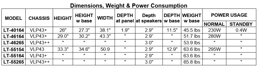
The VLP43,
VLP43+ and VLP43++ chassis types. The specific models for each chassis type,
dimensions and weight are listed below.

Cold Check
With
the alternating current (AC) plug removed from the AC source, place a jumper
across the two AC plug prongs. Connect one lead of an ohm meter to the AC plug
and touch the other lead to each exposed metal part (i.e. antennas, handle bracket,
metal cabinet, screw heads, metal overlay, control shafts, etc.), particularly
any exposed metal part that has a return path to the chassis. The resistance of
the exposed metal parts having a return path to the chassis should be a minimum of 1Meg Ohm. Any
resistance below this value indicates an abnormal condition and requires
corrective action.
2. Hot Check ...Use the circuit shown below to perform the hot check test.
1. Keep switch S1 open and connect the receiver to the measuring circuit.
Immediately after connection, and with the switching devices of the receiver in
their operating positions, measure the leakage current for both positions of
switch S2.
2. Close switch S1, energizing the receiver. Immediately after closing switch
S1, and with the switching devices of the receiver in their operating
positions, measure the leakage current for both positions of switch S2. Repeat
the current measurements of items 1 and 2 after the receiver has reached
thermal stabilization. The leakage
current must not exceed 0.5 milliamps (mA).


REMOTE CONTROL
USE FOR SERVICE
Many
service functions and adjustments are accessed using the Remote Control.
OPTION MENU
1.
Press the <MENU> button on the remote control.
2. Press the buttons <2-4-7-0>. The screen will display the Option Menu.
3. Press <EXIT> to quit.
SERVICE LEVEL INITIALIZATION
Service
Level Initialization is used to restore all customer menu, video and audio
settings to the original factory default condition.
1. Enter the Option Menu <MENU> <2-4-7-0>.
2. Select “Initialize” and <ENTER>
DEACTIVATE VUDU (Software Version 12.08 and higher)
This feature will deactivate the customer’s VUDU on-line subscription. It
should be used before TV ownership is changed.
NOTE: This feature is independent of the Initialize function.
1. Enter the Option Menu <MENU><2-4-7-0>.
2. Select “Deactivate Vudu” and
<ENTER>.
3. The “Deactivate Vudu” text will momentarily turn red.
4. Press <EXIT> to quit.
5. The TV will register as deactivated the next time it is connected to the
internet.
DIGITAL SIGNAL INFORMATION
Information
on the currently selected digital channel can be displayed on screen.
Note: A digital channel received using the Antenna Input must be selected
first.
1. Select the Antenna Input and an active digital channel.
2. Enter the Option Menu <MENU> <2-4-7-0>.
3. Select “Digital Signal Strength” and <ENTER>.
4. Press <EXIT> to quit.

RESET / INITIALIZATION
Many customer
generated symptoms, intermittent symptoms or no symptom found can be resolved
by using the various Reset and Initialization options. Before visiting the
customer’s home ask the customer 1st perform a System Reset by pressing the
<POWER> button on the front panel and holding it for 8 seconds. If this
does not resolve the issue, they can perform an A/V Reset by pressing the <INPUT> +
<VOL e> buttons on the front panel at the same time and holding for 10
seconds. Then, if necessary, perform a user level Initialization by pressing
<MENU><1-2-3> <ENTER> with the remote. The customer should be
made aware when settings and/or options will be reset. For more information,
see the chart below

BACKUP / RESTORE ISF SETTING
VLP43+ and
VLP43++ models - If the customer has calibrated the ISF (ADV) video settings,
the settings data can be backed up on a USB memory device. If the settings are
lost due to a Reset or Initialization procedure, PWB-MAIN replacement or other
reasons, the settings data can be restored.
Backup ISF Settings.
1. Insert a empty USB memory device into the USB slot.
2. Press the <MENU> button on the remote control. The Customer Menu will
appear.
3. Press the <2-4-5-7> buttons. The Service Menu will appear.
4. Press the <0> button. The Data Selection Menu will appear. See below.
5 Use the
<Up or Dn> buttons to select “BACKUP AND RESTORE ISF SETTING” and press
<ENTER>.
6 Use the <Up or Dn> buttons to toggle to "Backup ISF Settings to
USB” (Default)
7. While
"Backup ISF Settings to USB” is displayed, press <ENTER>. The screen
will flash the message "Backup completed."
8. Remove the
USB memory device and store it in a safe place.
9. Press <MENU> to exit

Restore ISF Settings.
1.
Insert the USB memory device with the backup data into the USB slot.
2. Press the <MENU> button on the remote control. The Customer Menu will
appear.
3. Press the <2-4-5-7> buttons. The Service Menu will appear.
4. Press the <0> button. The Data Selection Menu will appear. See above.
5. Use the <Up or Dn> buttons to select “BACKUP AND RESTORE ISF SETTING”
and press <ENTER>.
6. Use the <Up or Dn> buttons to toggle to “Restore ISF Settings From
USB.”
WARNING: DO NOT press
<ENTER> while "Backup ISF Settings to USB" is displayed. The
data on the USB will be overwritten and lost.
7. While
“Restore ISF Settings From USB” is displayed, press <ENTER>. The screen
will flash the message "Restore completed." The TV will then turn
off.
8. Remove the
USB memory device before turning the TV back on.

To SET SCREEN SIZE
The same
PWB-MAIN is used for different screen sizes within a chassis family. When a
PWB-MAIN is replaced, the screen size must be set up. Failure to setup the
correct screen size will result in poor picture performance.
1. Press the <MENU><2-4-5-7> buttons. The Service Menu will appear.
2. Press the <0> button. The Data Selection Menu will appear.
3. Use the <Up or Dn> buttons to select “SET SCREEN SIZE” and press
<ENTER>.
4. Use the <Up or Dn> buttons to toggle to select the correct screen size
and chassis of the model being serviced.
5. Press <ENTER>.
6. The Screen Size indication will flash Red momentarily to indicate the
selection has been saved.

LED INDICATIONS AND SELF DIAGNOSTICS
The front panel
Status LED provides an indication of the set’s operation and the possible cause
of a malfunction.
A blinking red
and yellow Status LED will indicate an Error Code that can help determine the
cause of a circuit failure.
• The number of Red blinks indicates the value of the MSD (tens digit) of the
Error Code.
• The number of Yellow blinks indicates the value of the LSD (ones digit) of
the Error Code.
Example: If the Error Code is “27”, the LED will continuously blink Red two
times, followed by blinking Yellow seven times.
To perform a
System Reset, press and hold the side Power button for 10 seconds. Or, unplug
the set for 10 seconds then restore power

Error codes and
error code log
ERROR CODE LOG
The
Error Code Log may be helpful to retrieve the code for an error that occurred
in the past.
To access the Error Code Log: Press <MENU> <3-5-6-4>
Error Code Definitions
•
PAGE - Current page number
• CURRENT TIME - total hours of operational use.
• USAGE TIME - usage hours when the error occurred.
• CODE - the specific Error Code that occurred.
• STATUS: HAPPENED - Indicates an error was recorded.
Press <CANCEL> to erase the Log.
NOTE: The Error Code Log is intended as a reference tool and is not meant to be
used as a final determination of a defective part.

SOUND PROJECTOR TRANSDUCER TEST
This procedure will test will each of the TV’s speakers individually using an
internal white noise generator.
1.
Press the <MENU> button on the remote control. The Customer Menu will
appear.
2. Press the <2-4-5-7> buttons. The Service Menu will appear.
3. Press the <0> button. The Data Selection Menu will appear. See below.
4. Use the
<Up or Dn> buttons to select “SOUND PROJECTOR TRANSDUCER TEST” and press
<ENTER>. The Sound Projector Transducer Test Menu will be displayed. A
tone will automatically cycle from one speaker to the next as indicated on
screen. Follow the instructions to manually cycle the tone.
5. Press <EXIT> or <MENU> to exit.
NOTE: The VLP43 chassis has 12 speakers. The menu will show 16 speakers with 4 greyed
out.
The VLP43++ chassis includes left and right full range speakers.

