Tuesday 30 November 2021

Haier 40DR3505 LED TV-MSD3393LU Chassis – how to enter the service mode, how to disassemble, amplifier schematic


How to disassemble the TV

Remove the Stand

Remove the Back Cabinet

Remove the power-main board.

Remove the Speaker

How to remove the stand

1. Lay down the TV set .
2. Remove the four screws from the stand which in the picture.
3. Remove the stand.

Remove the Remote Control Board And the Key Board


How to remove the back cabinet.

1. Remove the fifteen screws indicated with red circles.
2. Flip machine, panel side up.
3.Carefully raise the Front shell from bottom.


How to remove the power-main board.

1. Remove the six screws indicated with red circles.
2. Then remove the side metal board and down metal board.
3. Remove the four screws indicated with red circles.
4. Remove the power-main board.

How to remove the speaker

Remove the speaker directly

How to remove the remote control board and the key board

Connectors definition

LVDS Interface connector

Amplifier schematic

How to enter into Service Mode
The way to the factory mode menu:
Step 1: Press Menu,
Step 2: Press “8893”,
System will be into the factory mode menu when 2 steps above are done.
At the end of the main factory menu, you can see the edition of the software, like this" BUILD TIME 2014-01-21 23:17:21 VERSION v1.0 ”.

How to exit
If you want to exit this factory menu, please press the button ”Exit” on the remote.
System will be out the factory mode menu.

In factory mode menu, press up/down button to choose the up/down item, press right or OK button to the submenu. Press MENU button to go back.

GENERAL SETTING
1)Init Flash;
2)Uart Enable: Choose on or off in Uart Enable;
3)Dbg Message Enable: Choose on or off in Dbg Message Enable;
4)Test Pattern: Choose the Pattern picture;
5)Dynamic Contrast: Choose on or off in Dynamic Contrast;
6)Power On Mode: Choose on or off in Power On Mode;
7)Mirror Control: Choose on or off in Mirror Control;
8)Front End Status
9)Timer Test
10)SSC
11)Erase Flash
12)PQ Advance Debug: Choose on or off in PQ Advance Debug;
13)Factory remote:
Open or close the
Factory remote;

Panel Setting
1)LVDS Bit Mode: choose the Bit;
2)LVDS MAP: choose the MAP;
3)LVDS ODD/Even: choose ODD or Even;
4)Bcaklight:Adiust the
value of backlight;
5)Reset Panel Setting Date
6)6MX0 LVDS Map:
choose the 6MX0 LVDS MAP;
7)
6MX0 Channel: choose the 6MX0 Channel;
8)6MX0 Mirror:
choose the 6MX0 Mirror;
9)6MX0 Demo:
choose the 6MX0 Demo;
10)6MX0 Update.

Main board

1. Mainchip—MSD3393LU(U1)
2. Audio Amplifier
TPA3110D2PWPR (UA1)
3.Main Flash Memory—
GD25Q32BSIG (UF1)
4.DC/DC convertor 5V-1.8V for MSD3393LU (U1)—
LC1117CLTRAD (UL2)
5.voltage convertor 5V to 3.3V_STB —
LC1117CLTR33 (UL1)
6.voltage convertor 5V to 1.15V_STB —
LC3406CB5TR (UD1)
7.voltage convertor 5V to 3V for tuner—
LC1117CLTR33 (UT1)
8.Tuner —
SDCL1005CR33JTDF (RFT1)


Saturday 9 October 2021

Akai 21CT32FSR CRT TV – service mode, adjustments, circuit diagram - TDA9381 and KASQ1265 as Power switching


Adjustment method

Main power +B setting
Receive standard color pattern RF signal set picture to Standard Mode. Adjust VR501. to get +B (VD631 -) voltage =110 V
I2C bus control adjustment method:
enter and exit factory mode
For remote controller of factory

Continuous push [test] key on  the remote controller, the TV mode will change as: Normal  è  M  è BUS OPEN

 You can select “M” ( factory mode ) or “normal” mode.

For remote controller of user
Push [menu] key,
display picture manual → push digital key 8500 → display M. Push [standby] key, exit factory mode and TV will be standby.

MENU 8 Geometrical adjustments.
Receive standard Crosshatch pattern signal for PAL system .
Horizontal line
Shadow
1) Adjust VSLOPE value
to the horizontal line just appear from half bottom shadow.
2) Adjust VSHIFT value
the centre horizontal line correspond to CRT vertical centre.
3) Adjust Vamp value
to get 90% of vertical picture contents would be displayed on CRT.
4) Adjust HSHIFT value
to get the picture horizontal centre correspond to CRT horizontal centre.
5) Receive standard Crosshatch pattern signal for NTSC system, and again adjust.

MENU 7 AGC-TOP adjustment
Receive 60dBu (1mv)VH colour bar signal adjust AGC valuevoltage from high to low), to picture noise reduce gradually to be just disappeared.

MENU 9 CRT cut-off and white balance and sub-brightness adjustment.
Receive gray and white 2 steps signal.
a) CRT cut off adjustment.
1. push [▲P+][▼P-] key to select “SC”, push [►V+][◄V-] key then automatically vertical scan will be stopped.
2. Adjust SCREEN control on Flyback transformer to get the darkest single horizontal line (red
green, or blue, sometimes shows more yellowmore purple or more white).
3. Push [V+][V-] key again, vertical scan work repeat.

b) White balance adjustment.

1. Select RD/BD menu.
2. Adjustment RD/BD to get color temperature as x=281, y=311.
c) sub-brightness adjustment (use stair case signal)
1. Select SB MENU.
2. Adjust SB to get the darkest step being on or off.

MENU 6 Set SHIP MODE
Select “SHIPMODE”, push [V+][V-]key may be shipped.
Note:: may increase the screen of FBT current, the darkling single ought no fly back line, AV state.

I2C bus control adjustment item default setting (21 inch)


Note1:
TEXT DEF : TXT_def = 0: Pan_Euro + Cyrillic
= 1: Farsi English + French + Turkish
= 2: Arabic + English + French + Turkish
= 3: UKRAINIAN
Attention:
When TXT_def=0, will appear" the TXT LANGUAGE" in the customer Setup menu, press V+/ V- key," the TXT LANGUAGE" will appear the following circulation: W- TR-> EAST1-> EAST2-> W- TR
The W- TR diagram text includes the following language:
English German Swedish/Fin/Dan/Hungarian Italian French Spanish/Portuguese Turkish The EAST1 diagram text includes the following language:
Polish German Estonian Slovenian Czech/Slovak Rumanian
The EAST2 diagram text includes the following language:
Polish German Swedish/Fin/Dan/Hungarian Lettish Russian Slovenian Czech/Slovak Estonian
Note 2:
Make use of 4 color keys of the remote control, browse 4 pages of the enactment quickly, namely index function.
The TV/ AV sets the saving key for the index.
While using this function," the TXT LIST" establishes for" ON" in the customer menu.
Example: if want to use the color key of the red quickly 230 pages of enter the diagram text
The sequence press" TEXT"," red key","2","3","0" on the remote control," TV/ AV"
Note 3:
Switch on the hour appearance constitution
0: connect the AC power, enter to need the machine appearance automatically
1: connect the AC power, automatically switch on appearance
2: connect the AC power, if shut down the appearance as the diagram text appearance, enter the diagram text appearance automatically.

SCHEMATIC DIAGRAM

The main chips instruction. TDA93X1
The UOC (“Ultimate One Chip”) TDA93X1 is adopted in this chassis. This IC is the first available component that contains the complete control and small signal functionality needed for a TV application in one device.
The UOC TDA93X1 pins function description
:(total 64 pins
Pin1: Standby control,1is on,0is off.
Pin2: SCL.
Pin3: SDA.
Pin4: Tuning PWM output.
Pin5: Auto AV control SW/NTSC SW,
Pin6: Key board input.
Pin7: Volume
Pin8: Mute control,
1is mute,0is off.
Pin9: Pin12
, Pin18, Pin30, Pin35, Pin41, Pin55: GND.
Pin10: BAND1 control output.
Pin11: BAND2
Pin12: GND
Pin13: SECAM PLL, connected with a capacitance.

Pin14: +8V power source supply.
Pin15: Using a capacitor of 220n in series to GND, This pin decouples the internal digital supply voltage of the video processor and minimizes the disturbance to the sensitive analogue parts.
Pin16: PHI-2 control loop, this pin requires a capacitor at 2.2nF (C) in series to GND.
Pin17: PHI-1 control loop, the loop filter connected to pin 17 is suitable for various signal conditions  strong/weak and VCR signal. This is achieved by switching of the loop filter time constant y changing the PHI-1 output current.
Pin18: GND.
Pin19: Band gap decoupling, the band gap circuit provides a very stable and temperature independent reference voltage. This reference voltage (4.0 V) ensures optimal performance of the analogue video processor part of the N301 and is used in almost all functional circuit blocks.
Pin20: East-west pillow signal output.
Pin21: Pin22
Vertical drive output.
Pin23: Pin24
IF input
Pin25: Reference current, This pin requires a resistor to ground. The optimal reference current is 100mA which is determined by this resistor. The 100mA reference current should not be changed because the geometry processor is optimised for this current. Furthermore the output current of vertical drive and EW are proportional to this current.
Pin26: Vertical saw tooth, This pin requires a capacitor to ground of 100nF
Pin27: AGC output. This output is used to control (reduce) the tuner gain for strong RF signals.
Pin28: Audio de-emphasis.
Pin29: Sound decoupling. This pin requires a capacitor connected to ground. The pin acts as a low pass filter needed for the DC feedback loop.
Pin30: GND.
Pin31: Sound loop filter.
Pin32: AVL filter.
Pin33: Horizontal drive signal output, needs a resistor in series to +8V.
Pin34: Sandcastle output/fly back input,
Pin35: External audio input, this pin should be grounded in this chassis.
Pin36: EHT tracking/ overvoltage protection. If something is wrong, the anode high voltage rises, the heater voltage will rise too. When the rising voltage arrive some limit, the VD461 works, the voltage of pin 36 will exceed 3.9V, the N301will stop working.
Pin37: PLL loop filter.
Pin38: CVBS output. Monitor or RF videos can be selected.

Pin39: +8V supply source.
Pin40: CVBS input
Pin42: Y signal input.
Pin43: C signal input.
Pin44: Main audio output
Pin45: RGB signal input blanking.
Pin46, Pin47, Pin48: RGB signal input.
Pin49: ABL. It means been current limiter input. The R464 is the control resister.
Pin50: Black current input from the CRT board.
Pin51, Pin52, Pin53: RGB drive signal output to the CRT board.
Pin54: +3.3V.
Pin55: GND.
Pin56: +3.3V.
Pin57, Pin58, Pin59: 12MHz crystal

Pin60: Reset, NC in this chassis.
Pin61: +3.3V
Pin62: This pin is connected to the HEF4052, Functions expanding.
Pin63: This pin is connected to the HEF4052, Functions expanding.
Pin64: IR signal input.


Memory AT24C08 is an E2PROM of 8k, pins describe as follows:
Pin1, Pin2, Pin3,Pin4, Pin7: GND. Pin8: +5V supply.
Pin5: SDA. Pin6: SCL.


Wednesday 29 September 2021

Rolsen RL 32D40D, Philips 715G6934P, GRADIENTE P1 Amp and RAG7 820.5338 Power board schematic


Philips 715G6934P01002002H [32 inch LCD TV SMPS] schematic


ROLSEN RL32D40D, RL32D40D, RL32D50D, RL32D60D - SMPS (Power board) schematic


RSAG7 820.5338 Power board schematic


Gradiente P1  Amp schematic


Monday 20 September 2021

Toshiba 32A36C-service mode- full schematic diagram and waveforms


After turning the power off there might still be a potential voltage that is very dangerous. When removing the Anode Cap, make sure to discharge the Anode Cap's potential voltage.
Do not use pliers to loosen or tighten the Anode Cap terminal, this may cause the spring to be damaged.

Removal procedure of anode cap

Connect one end of an Alligator Clip to the metal part of a flat-blade screwdriver and the other end to ground.
While holding the plastic part of the insulated Screwdriver, touch the support of the Anode with the tip of the Screwdriver.
A cracking noise will be heard as the voltage is discharged.


SERVICE MODE – How to enter

This unit provided with the following SERVICE MODES so you can repair, examine and adjust easily.
To enter the Service Mode, press both set key and remote control key for more than 1 second.

CONFIRMATION OF HOURS USED
POWER ON total hours can be checked on the screen. Total hours are displayed in 16 system of notation.
NOTE: If you set a factory initialization, the total hours is reset to "0".

Set the VOLUME to minimum.
Press both VOL. DOWN button on the set and Channel button (6) on the remote control for more than 1 second.
After the confirmation of using hours, turn off the power.


WHEN REPLACING EEPROM (MEMORY) IC

If a service repair is undertaken where it has been required to change the MEMORY IC, the following steps should be taken to ensure correct data settings while making reference to TABLE

Enter DATA SET mode by setting VOLUME to minimum.
Press both VOL. DOWN button on the set and Channel button (6) on the remote control for more than 1 second.
ADDRESS and DATA should appear as FIG 1

ADDRESS is now selected and should "blink". Using the VOL. UP/DOWN button on the remote, step through the ADDRESS until required ADDRESS to be changed is reached.
Press ENTER to select DATA. When DATA is selected, it will "blink".
Again, step through the DATA using VOL. UP/DOWN button until required DATA value has been selected.
Pressing ENTER will take you back to ADDRESS for further selection if necessary.
Repeat steps 3 to 6 until all data has been checked.
When satisfied correct DATA has been entered, turn POWER off (return to STANDBY MODE) to finish DATA input.
After the data input, set to the initializing of shipping.
Turn POWER on.

Press both VOL. DOWN button on the set and Channel button (1) on the remote control for more than 1 second.
After the finishing of the initializing of shipping, the unit will turn off automatically.

The unit will now have the correct DATA for the new MEMORY IC.


Schematic diagram and printed circuit board


Microcontroller schematic diagram


Chroma section schematic

Deflection section schematic

Power [SMPS] schematic

Sound section schematic

Tuner section schematic

Audio-Video schematic

CRT socket section schematic

Comb filter schematic

AV jack schematic

Waveforms


Saturday 18 September 2021

Wednesday 25 August 2021

KALLEY K-LEDHDST2 LED TV – Service mode, factory mode, software update, power and amplifier schematic


K-LED32HDST2/MS08GP-LA/Smart TV/CSFGTA

Alignment Procedure-MS08GP Series-L32D2700/L40D2700

MS08GP These chassis are designed for Eastern Europe markets Ready for IPTV. The main chip is from Mstar and supports below features matrix:
Factory Menu:  Methods of Entering
Method 1: Using the remote control
Select “Picture” and press “OK” key to enter into Picture Mode press RIGHT” or “LEFT” key Select User Mode
Press the subsequence RCU keys “
9”, “7”, “3 and 5 will appear in the left top of screen In case of “Factory hotKey” is enabled On , just press RCU “Return” key to pop-up again the Factory menu.
The status of “Factory Key” can be changed in Factory Menu->Hotkey.
Press RCU “OK” key or “RIGHT” key to enter the submenu.
Press RCU “Menu” key to go back to the root menu.
Press RCU “RIGHT” or “LEFT” key to change the values.
Press RCU “OK” key run the function.
Press RCU “Exit” key exit the Factory menu.

Design Menu

Methods of Entering
Method 1: Using the remote, enter the “Picture” submenu in the OSD; choosing the “contrast” item and press the 1,9,5,and 0 in series ,Design Menu will appear in the left top of screen.
Method 2: Press RETURN button when DESIGN HOTKEY is enabled (ON).

Hotel menu

Service Menu
1.Methods of Entering
Using the remote, enter the “Picture” submenu in the OSD; choosing the “contrast” item and press the 9,7,0 and 5 in series, Service Menu will appear in the left top of screen.

Debugging
5.1. General Steps of debugging
According to the requirement of the order, below steps are needed for appropriate setting.
1) Enter the Factory Menu, enable FAC HOTKEY.
2) Check Project ID and the version of software, release date displayed at the bottom of Factory Menu.
3) Enter Design Menu, choose SERVICE MENU
èProject ID, choose corresponding Project ID number of the product (Refer to the “V6-PROJECT -ID0**”in the BOM list).
4) Return to Factory Menu, check the Product model.
5) Choose Factory Menu->NVM RESET and press the right button of the remote and wait until prompt OK appears.
6) Restart the set
7) According to the requirement of the order, Set the items of SHOP INIT and Hotel Menu etc.

8) After aging under normal temperature, calibrate ADC and adjust white balance.

9) Choose Factory Menu ->SHOP and press the button of remote to initialize the set.
Note: After step 9, Hotel Menu will be disabled by default. Therefore, if the order requires hotel function, it is necessary to enable hotel function by set Design MENU->Service Menu->HOTEL ENABLE to ON.
Equipment
·Color Analyzer CA-210.
·Video Pattern Generator Chroma2329.
·Color TV Pattern Generator PM5418/Fluke5418.
·VGA cable , AV(RCA) cable , HDMI cable etc.


5.3. ADC Function

not Calibration


5.4. White Balance adjustments (Manual)


Before adjustment ,you must make sure the ADC status(only PC and YPbPr)


is

“success”and

Color

Analyzer

has

been

calibrated

.Only

AV1,YPbPr,PC,HDMI1 need to be adjusted. HDMI1 should be the first.
Signal and generator
The pattern of the signal should be used are White (Chroma2329 pattern 113) and Grey (pattern 114).
The format of signal are respectively 720P for HDMI1 (Chroma2329 Timing 69),PAL (Chroma2329 Timing38) for AV1,1024X768@60Hz(Chroma2329 Timing14) for VGA

Steps of adjustment
1).Enter the factory menu-> White Balance, select source HDMI 1 and Normal Temperature.
2).Input grey signal in 720p format.
3).Change R-OFFSET and B-OFFSET to make sure the value of color coordination equal to (X=0.270 +/-0.015;Y=0.290 +/-0.015).
4).Input white signal in 720p format.
5).Change R-GAIN and B-GAIN to make sure the value of color coordination equal to (X=0.270 +/-0.015;Y=0.290 +/-0.015).

6).Repeat step 2—5 until both of the value of color coordination of white and grey equal to (X=0.270 +/-0.015;Y=0.290 +/-0.015).
For COOL and WARM color temperature, just repeat step 2—5.The color coordination we recommend for COOL and WARM color temperature is respectively(X=0.270 +/-0.015;Y=0.270 +/-0.015) and (X=0.300 +/-0.015;Y=0.305 +/-0.015).
After the adjustment of HDMI1, you can switch to other source AV, PC and YPbPr and repeat step 1—6 to do the WB adjustment.
Note: For some small size LED panel,the color coordination of specifications is not X=0.270/Y=0.290,and we recommend you adopt the values from panel specifications.
 ADC Calibration and White Balance Adjustment (automatic)
The process of adjusting White Balance automatically is out of the range of this file, Please refer to the relevant technical file of HuiZhou factory of TCL.
6.Chip list of software programming before SMT
Following chips must be programmed before SMT by tools

Position

Chip type

Software description

U301

MT29F2G08ABAEA

HDMI HDCP Key, System Software etc.

Software update: Method of SW update:
1.Download the bin file to the root directory of your USB device (Do not change the file name); Then insert the USB device to USB interface of TV set.
MS08GPSeries with its upgrade file corresponding relation as the table below show:

Chassis Name

Sales
area

Upgrade filename

Remark

MS08GP

LA

MS08GP_MAIN.bin

DVB-T2

How to upgrade FLASH SW using USB

Copy the SW BIN image MS08GP_MBOOT.bin” into USB stick root path.
Note: If there’s already other “MS08GP_MBOOT.bin” into USB root, it needs to be deleted or renamed.

Plug USB stick to the TV USB slot.
Press RCU MENU
èOptionèSoftware upgradeèBy USBèConfirm.
Or, turn off the TV press and hold the power key of key board before reconnect AC cord to restart TV for 5-8seconds (Forced Upgrade).
When the "UPGRADING SOFTWARE" picture appears as below, it means TV is uploading SW BIN image. Waiting a few minutes.

When updating is successful, TV should restart automatically.
There are two methods to upgrade SW using USB, the first one like below
In the previous of upgrade SW using USB, should program mboot bin file
MS08GP_MBOOT.binby ISP_Tool or by USB. .
Then switch off TV by removing AC cord.
Copy the SW BIN image
MS08GP_MAIN.bin” for MS08GP into USB stick (pen
drive) root path
Note: If there’s already other The same name into USB root, it needs to be deleted or renamed
Plug USB stick to the TV
Press and hold the power key of key board before reconnect AC cord to restart TV for 5-8seconds.
Once USB stick starts blinking, TV is uploading SW BIN image.
When update is successful, TV should restart automatically.
Remember to perform “Factory menuÆNVM reset“ and then press RCU “OK” key
Switch off TV by removing AC cord
Reconnect AC cord to restart TV and wait few seconds for Eeprom update.

The second method
To use this method, there should be SW in mainboard to ensure TV can display normally.
Copy the SW BIN image
MS08GP_MAIN.binand into USB stick (pen drive) root path
Press RCU MENU
èOptionèSoftware upgradeèBy USèConfirm
TV display warning information, that means it is upgrading, almost 3minutes later, when upgrade successful, TV should restart automatically.

How to change Project ID with Remote Control Unit (RCU)

Process following subsequence IR codes to change project ID:
062598+MENU+xxx (xxx: Project ID, ex: 001)
Restart TV

How to upgrade MAC Address

Upgrading MAC address need to use the tool in factory and through serial command, the specific methods according to the operation of the factory guidance.

Instructions of Updating SW”
1. The following IC should be pre-copied before SMT process

Position

PART TYPE

Part Number

SW

U301
CPP

IC-TSOP48

13-FS29F2-G0B

Mboot, Main Software

2.The MAC Address, HDCP KEY, Device ID must be upgrade by debug port into U301.

Project ID selecting
1)Press the Menu button of remote control, then select Contrast item of Picture submenu; press 1,9,5,0 consecutively, there you go the Design Menu.
2) Select the SERVICE MENU item, press OK and RIGHT button of the remote to enter submenu,
3)Select the PROJECT ID item, press OK or RIGHT button of the remote to enter the submenu;
4)Press the right or left button of the remote to select the ID you want;
5)After ID selection, press MENU button of the remote to exit DESIGN MENU.
6)Finally, do AC power on/off.
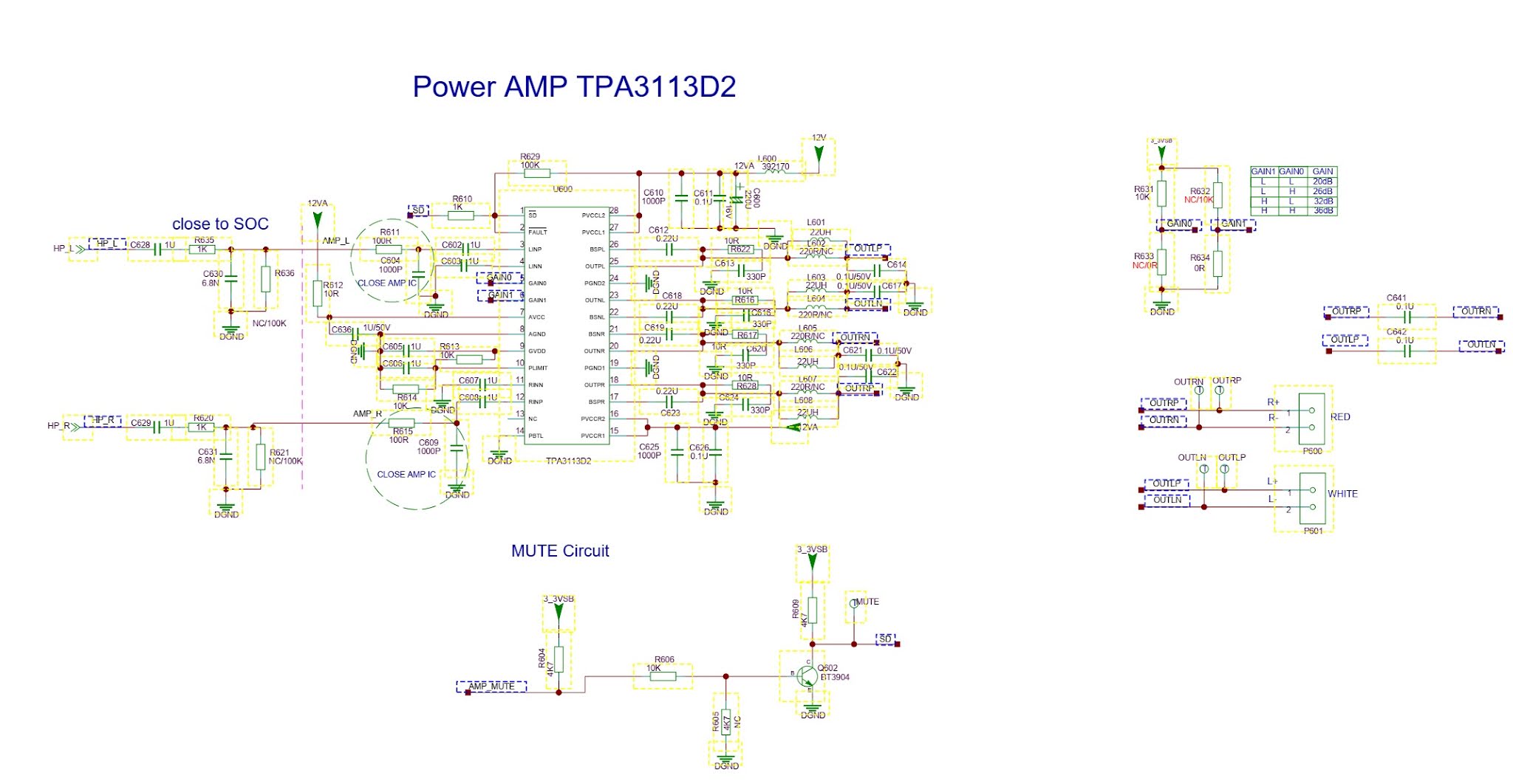
Schematic diagrams

Power supply (SMPS) schematic


Power distribution circuit


Power amplifier schematic– TPA3113D2


LG 52LG50FD, 52LG50FD-SA-Service adjustments-service mode entry-white balance adjustment-ADC component 1 RGB adjustment and more

  These adjustments are similar to 42LB7DF Because this is not a hot chassis, it is not necessary to use an isolation transformer. However...