Continuous RMS
power output (Reference) 50 W + 50 W (6 Ω at 1 kHz, 10% THD)
HCD-GRX20-RXD3
is the tuner, deck, CD and amplifier section in MHC-GRX20-RXD3.
CD Mechanism
Type: CX3
Base Unit
Type: KSM-213ECM
Optical
Pick-up Type: KSS-213ECM-C2NP
Tape Transport
Mechanism Type: CWL-44-FR
Continuous RMS
power output (Reference): 50 W + 50 W (6
Ω at 1 kHz, 10% THD
AM
tuner section
Tuning
range: 531 – 1,602 kHz (with AM tuning
interval set at 9 kHz) 530 – 1,710 kHz (with AM tuning interval set at 10 kHz)
Antenna: AM loop antenna
Antenna
terminals: External antenna terminal
Intermediate
frequency: 450 kHz
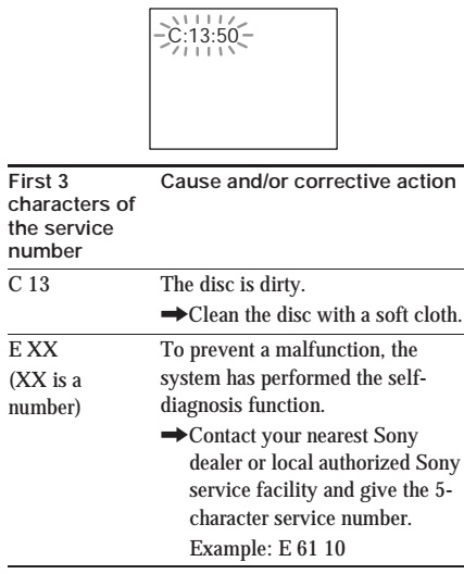
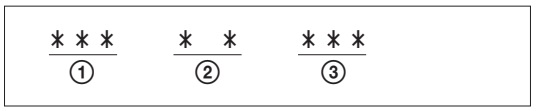
TEST
MODE
Initialization
STOP + POWER
OFF All preset data is re-set to the initial (default) value.
Model
display
STOP + DISC 1
Mode name is displayed.
Destination
display
STOP + DISC 2
Destination is displayed.
Version
display
STOP + DISC 3
Version number of the microprocessor is displayed.
CD
aging mode
STOP + DISC
SKIP/EX-CHANGE Set discs to DISC 1 and DISC 3. The following operations are
repeated when aging starts:
1. DISC 1: TOC
Read
2. Plays back
the last music of the DISC 1.
3. DISC 3 :
TOC Read
4. Plays back
the last music of the DISC 3.
5. STOP
6. Tray is
open and closed.
TAPE
aging mode
STOP + PLAY A
Insert a commercially available cassette tape (10 min) to the decks A and B.
When aging starts, each tape is rewound and the following operations are
repeated:
1. TAPE A: FWD
PLAY for one minute
2. TAPE A: FWD
STOP for one second
3. TAPE A: FWD
PLAY for three minutes
4. TAPE A: FWD
FF to tape end
5. TAPE B: FWD
PLAY for one minute
6. TAPE B: FWD
REC PAUSE for one second
7. TAPE B: FWD
REC for three minutes
8. TAPE B: FWD
FF to tape end
9. TAPE B: REV
PLAY for one minute
10. TAPE B:
REV REC PAUSE for one second
11. TAPE B:
REV REC for three minutes
12. TAPE B:
REV FF to tape end.
CD
service mode
STOP +
OPEN/CLOSE The message “CD S - -” is displayed on the screen. The sled is moved
to the outer circumference while the FF button is pressed. Also, the SLED is
moved to the inner circumference while the REW button is pressed. After
pressing the PLAY button, FOCUS is turned ON, CLV-S is set, TRACKING and SLED
servos are turned OFF and ADDRESS 3 = 3F, 37 is set.
Display
STOP + DBFB
All displays are turned ON.
Balance
adjustment value
STOP +
DISPLAY/DEMO The balance adjustment value is displayed.
Key
check
STOP + FILE
SELECT Function of the pressed key is displayed.
MECHANICAL
ADJUSTMENTS
1. Clean the
following parts with a denatured alcohol-moistened swab:
Record-playback
head, pinch rollers, erase head rubber
belts, capstan idlers.
2. Demagnetize
the record/playback head with a head demagnetizer.
3. Do not use
a magnetized screwdriver for the adjustments.
4. After the
adjustments, apply suitable locking compound to the parts adjusted.
5. The
adjustments should be performed with the rated power supply voltage unless
otherwise noted.

Torque
Measurement

ELECTRICAL
ADJUSTMENTS
DECK
SECTION: 0 dB=0.775V
1. Demagnetize
the record/playback head with a head demagnetizer.
2. Do not use
a magnetized screwdriver for the adjustments.
3. After the
adjustments, apply suitable locking compound to the parts adjusted.
4. The
adjustments should be performed with the rated power supply voltage unless
otherwise noted.
5. The
adjustments should be performed in the order given in this service manual. (As
a general rule, playback circuit adjustment should be completed before
performing recording circuit adjustment.)
6. The adjustments
should be performed for both L-CH and RCH.
Record/Playback
Head Azimuth Adjustment (Deck A, Deck B)
[Perform these
adjustments for both decks.]


AM
Tuning Voltage Adjustment
1. Set the
reception frequency of the unit to 530 kHz.
2. Adjust L105
for 1.2 ± 0.05 V reading on the DC voltmeter.
3. Set the
reception frequency of the unit to 1,710 kHz.
4. Confirm
that the voltage reading on the DC voltmeter is within 8.0 ± 0.5 V.
Adjustment
Location: MAIN board.
AM
Tracking Adjustment.
1. Tune the set
to 600 kHz.
2. Set the
output of AM RF SSG so that the input level of the set will become 60 dB
(µV/m).
3. Adjust L104
so that when the waveform on the oscilloscope is maximum, no noise appears.
4. Tune the
set to 1,400 kHz.
5. Adjust
TC102 so that when the waveform on the oscilloscope is maximum, no noise
appears.
Repeat the
procedures in each adjustment several times, and the tracking adjustment should
be finally done by the trimmer capacitors.
Adjustment
Location: MAIN board.
FM Tuned Level
Adjustment
1. Supply a 28
dB 98 MHz signal from the ANTENNA terminal.
2. Tune the
set to 98 MHz.
3. Adjust
SFR101 to the point (moment) when the TUNED indicator will change from going
off to going on.
Adjustment
Location: MAIN board

CD
SECTION
1. CD Block is
basically constructed to operate without adjustment. Therefore, check each item
in order given.
2. Use YEDS-18
disc (3-702-101-01) unless otherwise indicated.
3. Use an
oscilloscope with more than 10MΩ impedance.
4. Clean the
object lens by an applicator with neutral detergent when the signal level is
low than specified value with the following checks.
5. Adjust the
focus bias adjustment when optical block is replaced.
1. Connect
oscilloscope to test point TP (RF) on CD DECODER board.
2. Turned Power
switch on.
3. Put disc
(YEDS-18) in and playback.
4. Confirm
that oscilloscope waveform is clear and check RF signal level is correct or
not.
Note: Clear RF
signal waveform means that the shape “◊” can be clearly distinguished at the
center of the waveform.

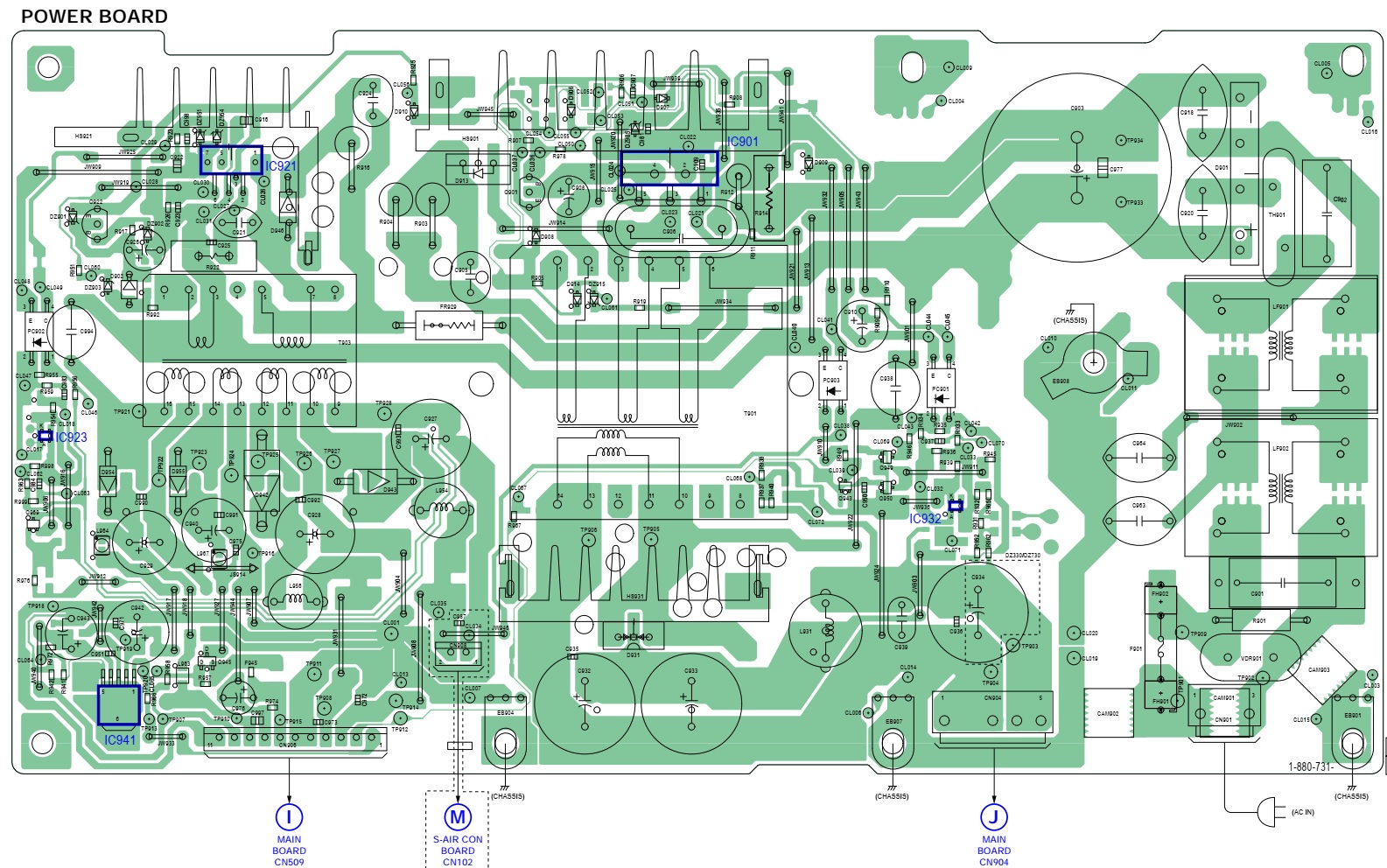
Circuit
diagrams