HBD-DZ330-DZ710-DZ730
are the amplifier, DVD-CD and tuner section in DAV-DZ330-DZ710-DZ730.
Model Name
Using Similar Mechanism:
HBD-DZ170-DZ171-DZ175-DZ310-DZ510-DZ610-DZ810.
Mechanism
Type: CDM85MB-DVBU102.
Optical
Pick-up Name: KHM-313CAA.
Amplifier
Section power output: Front L + Front:
108 W + 108 W (at 3 ohms, 1 kHz, 1% THD)
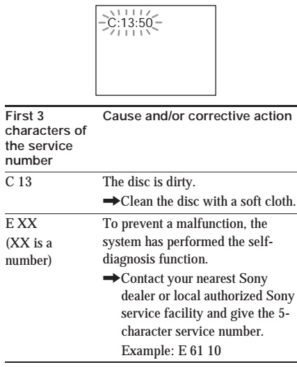
Self-diagnosis
Function.
(When
letters-numbers appear in the display)
When the
self-diagnosis function is activated to prevent the system from malfunctioning,
a 5-character service number (e.g., C 13 50) with combination of a letter and 4
digits appears on the TV screen or front panel display. In this case, check the
following table.

When
the version number appears on the TV screen.
When you turn
on the system, the version number [VER.X.XX] (X is a number) may appear on the
TV screen. Although this is not a malfunction and for Sony service use only,
normal system operation will not be possible.
Turn off the system, and then turn on the system again to operate.
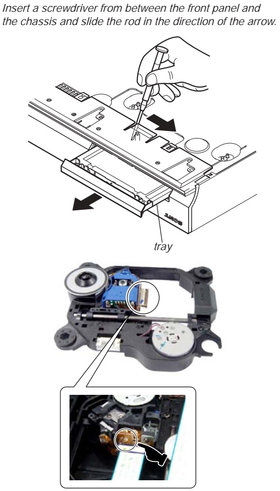
How to open
the disc table when power switch turns off Insert a tapering driver into the
aperture of the unit bottom, and slide it in the direction of the arrow.
Insert a
screwdriver from between the front panel and the chassis and slide the rod in
the direction of the arrow.
Precaution
when installing a new OP unit-Precaution before unsoldering the static
electricity prevention solder bridge.
When
installing a new OP unit, be sure to connect the flexible printed circuit board
first of all before removing the static electricity prevention solder bridge by
unsoldering. Remove the static
electricity prevention solder bridge by unsoldering after the flexible printed
circuit board has already been connected.
(Do not remove
nor unsolder the solder bridge as long as the OP unit is kept standalone.)
NOTES
ON HANDLING THE OPTICAL PICK-UP BLOCK OR BASE UNIT
The laser
diode in the optical pick-up block may suffer electrostatic break-down because
of the potential difference generated by the charged electrostatic load, etc.
on clothing and the human body. During
repair, pay attention to electrostatic break-down and also use the procedure in
the printed matter which is included in the repair parts. The flexible board is easily damaged and
should be handled with care.
NOTES
ON LASER DIODE EMISSION CHECK
The laser beam
on this model is concentrated so as to be focused on the disc reflective
surface by the objective lens in the optical pickup block. Therefore, when
checking the laser diode emission, observe from more than 30 cm away from the
objective lens.
LASER
DIODE AND FOCUS SEARCH
1. Open the
case and turn POWER on with no disc inserted.
2. Confirm that
the following operation is performed while observing the objecting lens from
the clearance of DVD mechanism deck.
1) Confirm
that laser beam is spread.
2) Up and down
motion of the objective lens. (2 times)
DISC
TRAY LOCK
The disc tray
lock function for the antitheft of an demonstration disc in the store is
equipped.
1. Press the
POWER button to turn the set on.
2. Press the
[FUNCTION] button to set DVD/CD function.
3. Insert a
disc.
4. Press the
[STOP] button and the [EJECT] button simultaneously for five seconds.
5. The message
“LOCKED” is displayed and the tray is locked.
Releasing Procedure:
1. Press the
[STOP] button and the [EJECT] button simultaneously for five seconds again.
2. The message
“UNLOCKED” is displayed and the tray is unlocked.
Note: When
“LOCKED” is displayed, the tray lock is not released by turning power on/off
with the [POWER] button.
IMPORTANT
NOTICE
Caution: This
system is capable of holding a still video image or onscreen display image on
your television screen indefinitely. If you leave the still video image or
on-screen display image displayed on your TV for an extended period of time you
risk permanent damage to your television screen. Projection televisions are especially
susceptible to this.
Discharge the
charged electricity in capacitors to prevent electric shock as follows
When
disassembling the machine, be sure to discharge the charged electricity in the
following capacitors. Use a resistor of 800 ohms, 2 Watts for discharging the
following capacitors.


TEST
MODE
Note:
Incorrect operations may be performed if the test mode is not entered
properly. In this case, press the
[POWER] button to turn the power off, and retry to enter the test mode.
1.
Cold Reset
• The cold
reset clears all data including preset data stored in the RAM to initial
conditions. Execute this mode when returning the set to the customers.
1. Press the
[POWER] button to turn the power on.
2. Press three
buttons [PLAY], [FUNCTION] and [POWER] simultaneously.
3. When this
button is operated, display as “COLD RESET” for a while and all of the settings
are reset.
2.
Panel Test Mode
• This mode is
used to check the software version, FL and KEY.
Display
Test Mode
1. Press the
[POWER] button to turn the power on.
2. While
pressing the [STOP] and the [PLAY] buttons simultaneously, turn the [VOLUME]
control in the direction of (+).
3. When the
display test mode is activated, all segments are turned on. When the mode in,
“REC TO USB” is turn off.
4. To exit
from this mode, while pressing the [STOP] and the [PLAY] buttons
simultaneously, turn the [VOLUME] control in the direction of (+).
Version
Test Mode
1. When the
display test mode is activated, press the [FUNCTION] button and the message
“DSZ2E” (DZ330), “DSZ6KD” (DZ710), “DSZ5E” (DZ730) are displayed, the version
test mode is activated.
2. Whenever
the [FUNCTION] button is pressed, the display changes in the following order.

3. Press the
[REC TO USB] button when the MC version is on display. The date of software
production is displayed.
4. Press the
[REC TO USB] button again and the version is displayed.
5. To exit
from this mode, while pressing the [STOP] and the [PLAY] buttons
simultaneously, turn the [VOLUME] control in the direction of (+).
FL
Pattern Test Mode
1. When the
display test mode is activated, press the [EJECT] button, to select the FL
pattern test mode. When the FL pattern test mode, half segments of FL display
and “REC TO USB” are turn on.
2. Press the
[EJECT] button, half segments of FL display and “REC TO USB” are turn off.
3. Next press
the [EJECT] button, all segments of FL display is turn on.
4. To exit
from this mode, while pressing the [STOP] and the [PLAY] buttons
simultaneously, turn the [VOLUME] control in the direction of (+).
Key
Test Mode
1. When the
display test mode is activated, press the [?/1] button, to select the key test
mode.
2. To enter
the KEY test mode, the fluorescent indicator displays “K0 V0”. Each time an
another button is pressed, “KEY” value increases. However, once a button is
pressed, it is no longer taken into account. When all keys are pressed
correctly, “K6 V0” is displayed.
3. When the
[VOLUME] control is turned in the direction of (+), “V0” is changed to “V1”,
then ... “V9”. When the [VOLUME] control is turned in the direction of (–),
“V0” is changed to “V9”, then ... “V1”.
4. To exit
from this mode, while pressing the [STOP] and the [PLAY] buttons
simultaneously, turn the [VOLUME] control in the direction of (+).
DVD
Version Display
• The STR and
DVD microprocessor versions are displayed.
1. Press the
[POWER] button to turn the set on.
2. Press the
[PLAY] button and the [POWER] button simultaneously for three seconds. SC
version display is presented.
3. Pressing
the [FUNCTION] button presents a DV version display. Pressing the [FUNCTION]
button again returns to the SC version display.
4. To exit
from this mode, press any button other than the [FUNCTION] button.
Product
Out
• This mode
moves the optical pick-up to the position durable to vibration and clears all
data including preset data stored in the STR RAM to initial conditions. Use
this mode when returning the set to the customer after repair.
1. Press the
[POWER] button to turn the power on.
2. Press the
[FUNCTION] button to set the function “DVD/CD”.
3. Remove all
discs.
4. While
pressing the [STOP] and the [EJECT] buttons simultaneously, turn the [VOLUME]
control in the direction of (+).
5. Displayed
to message “SERVICE IN” on the fluorescent indicator tube when pressing in turn
the [4] > [DVD MENU]
> [CLEAR] buttons on the
remote commander.
6. After the
“STANDBY” blinking display finishes, the message “MECHA LOCK” ó
“UNPLUG” is displayed on the fluorescent indicator tube disconnect the AC power
plug, then the product out mode is set.
The STR RAM
initialization is executed upon a next power-on after the power is turned off.
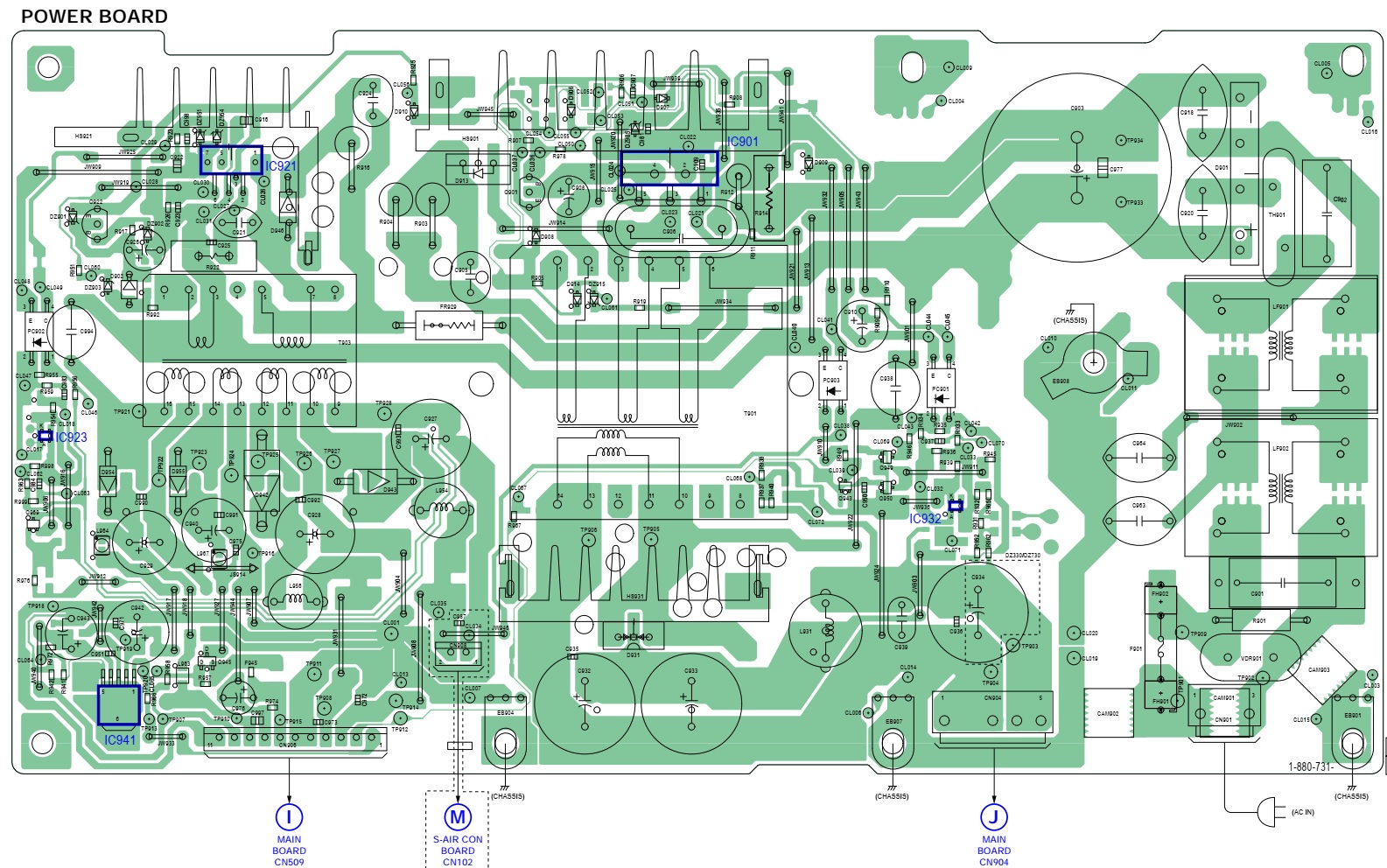
Power
board schematic

D.C.A.C.
(AUTOMATIC ACOUSTIC FIELD CALIBRATION) TEST MODE
1. Press the
[POWER] button to turn the power on.
2. Press the
[FUNCTION] button to set the function “ DVD-CD”.
3. Insert
Calibration mic (ECM-AC2) supplied as an accessory into the A.CAL MIC jack.
4. Press three
buttons [x], [Z] and [REC TO USB] simultaneously.
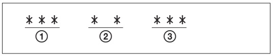
5. Confirm
that the following are shown on the display panel.
The
JACK inserted/non-inserted detection display and the display.
1 MIC
detection condition
NON : Not
detected
IN : Detected
2 Presence of
DIGITAL sound data input to the microprocessor
NG: Input
absent
OK: Input
present
3 AD value
(255h) of MIC input to the microprocessor.
6. To exit
from this mode, press three buttons [POWER], [EJECT] and [REC TO USB]
simultaneously.
7.
PROTECTION FACTOR (SD DETECTION-DC DETECTION-TSD DETECTION) IDENTIFICATION TEST
MODE
When an error
is detected, the FL tube alternately displays
“PROTECTOR<
-> PUSH POWER”.
Press the [POWER] button.
* Buttons
other than the [POWER] button are invalid.
“STANDBY” blinks
three times on the FL tube.
The protection
release state (POWER OFF) is established.
(No FL tube
display)
Press the [POWER] button two times.
The power to
the system turns on, and the normal operation is established. (Restore).
During the
protection state:
1. If the AC
plug is connected or disconnected during the protection state, the protection
state is released, and the normal operation is established. (The protection
state is not maintained.)
2. The
protection factor is displayed by pressing the [RETURN] > [3] > [2] >
[0] > [0] > [ANGLE] buttons of the remote commander.
(During the
“PROTECTOR” > “PUSH POWER” display).
When SD is detected: Repeats
“SD DETECT”
> “PROTECTOR”.
When DC is detected: Repeats
“DC
DETECT” > “PROTECTOR”.
When TSD is detected: Repeats
“TMP DETECT”
> “PROTECTOR”.
PL: SD
detection
When the “L”
output from the SD (shutdown) port on the S-MASTER POWER Driver Shutdown and
voltage descent (15V or less) of 30V power supply (PVDD) are detected.
DC detection
When the “L”
output from the power/speaker error detection circuit (DC detection port) is
detected for two seconds continually, the power system other than that of the
FL tube is turned off, and the protection state is established.
TSD detection
When the “L”
output from the thermal shutdown port (TSDM) on the motor driver is detected.

No comments:
Post a Comment