Service Mode Function
MPU
controls the functions switching for each IICs through IIC bus in this chassis.
The following setting and adjustment can be adjusted by remote control in
Service Menu
How
to enter into Service Mode
While
pressing [VOLUME ( - )] button on the main unit, press the [RED] button on the
remote control for 3 times within 2 seconds.
How
to exit
Switch
off the power with the [POWER] button on the main unit or the [POWER] button on
the remote control.


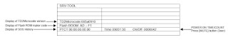
Service Tool Mode
How to access
1.
Select [SRV-TOOL] in Service Mode.
2. Press [OK] button on the remote control.
Display of SOS History
SOS
History (Number of LED blinking) indication.
From left side; Last SOS, before Last, three occurrence before, 2nd occurrence
after shipment, 1st occurrence after shipment.
This indication will be cleared by [Self/check indication and forced to factory
shipment setting].
Power
ON Time, On/Off
Note:
To display TIME/COUNT menu, highlight position, then press MUTE for 3sec.
Time: Cumulative power on time, indicated hour: minute by decimal.
On/Off: Number of On/Off switching by decimal.
Note: This indication will not be cleared by either of the self-checks or any
other command.
Exit
Disconnect
the AC cord from wall outlet or switch off the power with [Power] button on the
main unit.
Hotel Mode
1.
Purpose
Restrict a function for hotels.
2. Access command to the Hotel mode setup menu.
In order to display the Hotel mode setup menu, please enter the following
command (within 2 second).
[TV] : Vol.[Down] + [REMOTE] : AV (3 times) Then, the Hotel mode setup menu is
displayed.
3. To exit the “Hotel mode”:
Switch off the power with the [POWER] button on the main unit or the [POWER]
button on the remote control.
4. Explain the Hotel mode setup menu.

Data Copy by USB Memory
Purpose
a) Board replacement (Copy the data when exchanging A-board):
When
exchanging A-board, the data in original A-board can be copied to USB Memory
and then copy to new A-board.
b) Hotel (Copy the data when installing a number of units in hotel
or any facility):
When
installing a number of units in hotel or any facility, the data in master TV
can be copied to USB Memory and the copy to other TVs.
Preparation
Make
pwd file as startup file for (a) or (b) in an empty USB Memory.
1. Insert an empty USB Memory to your PC.
2. Right-click a blank area in a USB Memory window, point to New, and then
click text document. A new file is created by default (New Text Document.txt).
3. Right-click the new text document that you just created and select rename,
and then change the name and extension of the file to the following file name
(a) or (b) and press ENTER. File name:
(a) For Board replacement: boardreplace.pwd
(b) For Hotel: hotel.pwd
Note:
Please make only one file to prevent the operation error.
No any other file should be in USB Memory.

Panasonic LCD TV - LED blinking codes, How to enter the service mode,
Data copy, Option bytes, Self check and Power board [TNPA5852] schematic - TX-L32E6E-LA41
Chassis
Data Copy from TV set to USB Memory
1.
Turn on the TV set.
2. Insert USB Memory with a start-up file (pwd file) to USB Terminal.
On-screen Display will be appeared according to the start-up file
automatically.
3. Input a following password for (a) or (b) by using remote control.
(a) For Board replacement: 2770
(b) For Hotel: 4850
Data will be copied from TV set to USB Memory.
It takes around 2 to 6 minutes maximum for copying.
4. After the completion of copying to USB Memory, remove USB Memory from TV
set.
5. Turn off the TV set.
Note:
Following new folder will be created in USB Memory for data from TV set.
(a) For Board replacement: user-setup
(b) For Hotel: hotel

Data Copy from USB Memory to TV set
1.
Turn on the TV set.
2. Insert USB Memory with Data to USB Terminal.
On-screen Display will be appeared according to the Data folder automatically.
3. Input a following password for (a) or (b) by using remote control.
(a) For Board replacement: 2771
(b) For Hotel: 4851
Data will be copied from USB Memory to TV set.
4. After the completion of copying to USB Memory, remove USB Memory from TV
set.
(a) For Board replacement: Data will be deleted after copying (Limited one
copy).
(b) For Hotel: Data will not be deleted and can be used for other TVs.
5. Turn off the TV set.
Note:
1. Depending on the failure of boards, function of Data for board replacement
does not work.
2. This function can be effective among the same model numbers.

Option Bytes Description

Self Check
How to access
Self-check
indication only:
While pressing [VOLUME ( - )] button on the main unit, press [OK] button on the
remote control.
Self-check indication and forced to factory shipment setting:
While pressing [VOLUME ( - )] button on the main unit, press [MENU] button on
the remote control for more than 3 seconds.
How
to exit
Switch
off the power with the [POWER] button on the main unit.
[If the CCU ports have been checked and found to be incorrect or
not located then " - - " will appear in place of "O.K.".]

Power LED blinking timing chart
1.
Subject
Information of LED Flashing timing chart.
2. Contents
When abnormality has occurred the unit, the protection circuit operates and
reset to the stand by mode. At this time, the defective block can be identified
by number of blinking of the Power LED on the front panel of the unit.
LCD Panel Test Mode
Purpose:
To
find the possible failure point where in LCD Panel or Printed Circuit Board
when the abnormal picture is displayed.
How
to Enter:
While
pressing [VOLUME ( - )] button of the main unit, press [YELLOW] button of the
remote control three times.
How
to Exit:
Switch
off the power with the [POWER] button on the main unit or the [POWER] button on
the remote control.
How
to confirm:
If
the abnormal picture is displayed, go into LCD Panel test mode to display the
several test patterns.
And then, judge by the following method.
Still abnormal picture is displayed: The cause must be in LCD Panel.
Normal picture is displayed: The cause must be in A board.
Remarks:
The
test pattern is created by the circuit in LCD Panel.
In LCD Panel test mode, this test pattern is displayed unaffected by signal
processing for RF or input signal.
If the normal picture is displayed, LCD Panel must be okay and the cause of
failure must be in A board.

Adjustment Method

Power board schematic [TNPA5852]


