HCD-DX375 is the
amplifier, DVD/CD and tuner section in DAV-DX375.
Model Name Using Similar
Mechanism: HCD-DX255
Mechanism Type: CDM81C-DVBU101
Optical Pick-up Name: KHM-310CAB
AUDIO POWER SPECIFICATIONS
POWER
OUTPUT AND TOTAL HARMONIC DISTORTION
(FTC Output Power): FL/FR/SL/SR/C: 84 W/ch 3 ohm at 170 - 20,000 Hz, 0.7 % THD
SW: 160 W 1.5 ohm at 40 - 170 Hz, 0.7 % THD
Amplifier section
Surround
mode (reference) RMS output power, 10 % THD
Front: 143 W + 143 W (with SS-TS52)
Centre*: 143 W (with SS-CT51)
Surround*: 143 W + 143 W (with SS-TS51)
Subwoofer*: 285 W (with SS-WS52B)

LASER DIODE EMISSION CHECK
The laser beam on this
model is concentrated so as to be focused on the disc reflective surface by the
objective lens in the optical pickup block. Therefore, when checking the laser
diode emission, observe from more than 30 cm away from the objective lens
LASER DIODE AND FOCUS SEARCH
1.
Open the cover and turn POWER on with no disc inserted.
2. Confirm that the following operation is performed while observing the
objecting lens.
1) Confirm that laser beam is spread.
2) Up and down motion of the objective lens. (3 times)
DISC TRAY LOCK
The
disc tray lock function for the antitheft of an demonstration disc in the store
is equipped.
Press the POWER button to
turn the set on.
2. Press the [FUNCTION] button to set DVD function.
3. Insert a disc.
4. Press the STOP button and the EJECT button simultaneously for five seconds.
5. The message “LOCKED” is displayed and the tray is locked.
Releasing Procedure:
1.
Press the STOP button and the EJECT button simultaneously for five seconds
again.
2. The message “UNLOCKED” is displayed and the tray is unlocked.
Note 1: When “LOCKED” is
displayed, the tray lock is not released by turning power on/off with the POWER
button.
Note 2: Incorrect operations may
be performed if the test mode is not entered properly.
In this case, press the POWER button to turn the power off, and retry to enter
the test mode.
Note 3: If the disc tray does
not open and the message “LOCKED” appears, press the STOP button and the EJECT
button simultaneously for seconds or longer.
Then remove your fingers from the above stick and the button.
The message “UNLOCKED” appears for 2 seconds and the disc tray opens.
DMB12 board replacement
New
part of EEP ROM (IC103, IC706) on the DMB12 board cannot be used. Therefore, if
the mounted DMB12 board (A-1148-813-A) is replaced, exchange new EEP ROM
(IC103, IC706) with that used before the replacement.
Self-diagnosis Function
(When
letters/numbers appear in the display)
When
the self-diagnosis function is activated to prevent the system from malfunctioning,
a 5- character service number (e.g., C 13 50) with a combination of a letter
and 4 digits appears on the screen and the front panel display. In this case,
check the following table.
First
3 characters of the service number.
Cause and/or corrective action
C
13 The disc is dirty.
, Clean the disc
with a soft cloth
C 31 The disc is not inserted correctly.
, Restart the system,
then re-insert the disc correctly.
E XX (xx is a number) To prevent a
malfunction, the system has performed the self-diagnosis function. Contact your nearest Sony dealer or local
authorized Sony service facility and give the 5- character service number.
Example: E 61
When displaying the
version number on the screen.
When you turn on the system, the version number [VER.X.XX] (X is a number) may appear
on the screen. Although this is not a malfunction and for Sony service use
only, normal system operation will not be possible. Turn off the system, and then
turn on the system again to operate.
HOW TO OPEN THE DISC TABLE WHEN POWER SWITCH TURNS OFF. (During a power
failure or at emergency)

Discharge the charged electricity in capacitors to prevent electric shock as follows
When
disassembling the machine, be sure to discharge the charged electricity in the
following capacitors. Use a resistor of 800 ohms, 2 Watts for discharging the
following capacitors.

PRECAUTION WHEN INSTALLING A NEW OP UNIT / PRECAUTION BEFORE UNSOLDERING
THE STATIC ELECTRICITY PREVENTION SOLDER BRIDGE
When installing a new OP
unit, be sure to connect the flexible printed circuit board first of all before
removing the static electricity prevention solder bridge by unsoldering. Remove
the static electricity prevention solder bridge by unsoldering after the
flexible printed circuit board has already been connected. (Do not
remove nor unsolder the solder bridge as long as the OP unit is kept standalone.)

Test mode
Regarding the notification
symbol “R”
Because the number of the operating buttons of this product are limited, some
operations require use of the operating buttons of the remote commander, When a
specific operation requires use of the operating buttons of the remote commander,
“R” is added to the specific operating procedure in this manual. Example
MENU/NO “R” The MENU/NO button of remote commander. Incorrect operations may be performed if the
test mode is not entered properly. In
this case, press the POWER1 button to turn the power off, and
retry to enter the test mode.
Cold Reset
The
cold reset clears all data including preset data stored in the RAM to initial
conditions. Execute this mode when returning the set to the customers.
Procedure:
1. Press the POWER button to turn the power on.
2. Press three buttons STOP, EJECT and POWER simultaneously.
3. When this button is operated, display as “COLD RESET” for
a while and all of the settings are reset.
Panel Test Mode
This
mode is used to check the software version, FL, LED and KEY
Display
Test Mode
Procedure:
1.
Press the PWER button to turn the power on.
2. Press three buttons PAUSE , FAST REWIND and EJECT simultaneously.
3. When the display test mode is activated, all segments and LEDs
are turned on.
4. To exit from this mode, press three buttons PAUSE , FAST REWIND and EJECT
simultaneously.
Version Test Mode
Procedure:
1.
When the panel test mode is activated, press the FAST REWIND button and the
message “DCX3FD” is displayed, the version test mode is activated.
2. Whenever press the FAST REWIND button, the version is displayed in order of
NA, MC, SYS, UI, DVD, CDMA, CDMB, ST, TA, DSP and TM.
3. Press the FAST FORWARD button and the date of the software production is
displayed.
4. Press the FAST FORWARD button again and the version is displayed.
5. To exit from this mode, press three buttons PAUSE , FAST REWIND and EJECT
simultaneously.
Key Test Mode
Procedure:
1.
When the panel test mode is activated, press the PLAY button, to select the key
test mode.
2. To enter the KEY test mode, the fluorescent indicator displays “K0 V0”. Each
time a button is pressed, “KEY” value increases. However, once a button is
pressed, it is no longer taken into account. When all keys are pressed
correctly, “K13 V0” is displayed.
3. When the VOLUME control is turned in the direction of (+), “V0” is changed
to “V1”, then ... “V9”.
When the VOLUME control is turned in the direction of (–), “V0” is changed to
“V9”, then ... “V1”.
4. To exit from this mode, press three buttons PAUDE , FAST REWIND and EJECT simultaneously.
Disc Tray Lock
The
disc tray lock function for the antitheft of an demonstration disc in the store
is equipped.
Setting Procedure :
1. Press the POWER button to turn the set on.
2. Press the FUNCTION button to set DVD function.
3. Insert a disc.
4. Press the STOP button and the EJECT button simultaneously for five seconds.
5. The message “LOCKED” is displayed and the tray is locked.
Releasing Procedure :
1. Press the STOP button and the EJECT button simultaneously for five seconds.
again.
2. The message “UNLOCKED” is displayed and the tray is unlocked.
Note: When “LOCKED” is
displayed, the slot lock is not released by turning power on/off with the POWER
button.
DVD Ship Mode
Use
this mode when returning the set to the customer after repair.
Procedure:
1. Press the POWER button to turn the set on.
2. Press the FUNCTION button to set the function “DVD”.
3. Remove all discs, press two buttons STOP , and FAST REWIND simultaneously.
4. After a message “MECHA LOCK” is displayed on the fluorescent indicator tube,
pull out the AC plug.
5. To exit from this mode, press the POWER button to turn the set on.
AM Step Change
A
step of AM channels can be changed over between 9 kHz and 10 kHz.
Procedure:
1. Press the POWER button to turn the set ON.
2. Select the function “TUNER”, and press FUNCTION button to select the BAND
“AM”.
3. Press the POWER button to turn the set OFF.
4. Press two buttons FAST FORWARD and POWER simultaneously, and the display of
fluorescent indicator tube changes to “AM 9 k STEP” or “AM 10 k STEP”, and thus
the channel step is changed over.
Volume Test Mode
Procedure:
1.
Press the POWER button to turn the power on.
2. Press three buttons FAST REWIND, PLAY
and FAST FORWARD simultaneously.
3. The message “VOLUME MAX” is displayed, when the
VOLUME control is turned in the direction of (+).
The message “VOLUME MIN” is displayed, when the VOLUME control is turned in the
direction of (–).
4. To exit from this mode, press the POWER button to turn the set off.
Product out
This
mode moves the optical pick-up to the position durable to vibration and clears
all data including preset data stored in the RAM to initial conditions. Use
this mode when returning the set to the customer after repair.
Press the POWER button to
turn the power on.
2. Press the FUNCTION button to set the function “DVD”.
3. Remove all discs, and then press three buttons FAST FORWARD , EJECT and POWER
simultaneously.
4. After the “STANDBY” blinking display finishes, the message “MECHA LOCK” is
displayed on the fluorescent indicator tube disconnect the AC power plug, then
the ship mode is set.
TEST DISC LIST
Be
sure to use the DVD disc that matches the signal standards of your region.
• CD YEDS-18 (Part No.: 3-702-101-01) PATD-012 (Part No.: 4-225-203-01)
• DVD SL (Single Layer): NTSC : HLX-503 (Part No.: J-6090-069-A). HLX-504 (Part No.: J-6090-088-A), PAL : HLX-506 (Part No.: J-6090-077-A)
• DVD DL (Dual Layer): NTSC : HLX-501 (Part No.: J-6090-071-A). HLX-505 (Part No.: J-6090-089-A). PAL : HLX-507 (Part No.: J-6090-078-A)
GENERAL DESCRIPTION
The Mirror Time and IOP
measurement allows you to make diagnosis and adjustment simply by using the
remote commander and monitor TV. The instructions, diagnosis results, etc. are
given on the on-screen display (OSD).
Be sure to execute the Mirror Time and IOP measurement when a BU (Base Unit) is
replaced.
HOW TO ENTER TEST MODE
While
pressing the STOP and EJECT buttons simultaneously, turn VOLUME + with the DVD
player in power on.
The Test Mode starts, then the menu shown below will be displayed on the TV
screen.

The menu above is the
Remocon Diagnosis Menu screen which consists of six main function. At the
bottom of the menu screen, the model name and IF-con version. To enter Mirror
Time Adjustment menu, press button 2 “R” on the remote commander to enter Drive
Manual Operation menu. To exit from the Test Mode, press the power button on
the remote commander.
DRIVE MANUAL OPERATION
The
Drive Manual Operation menu consists of five main functions.
By pressing 2 “R” button on the remote commander in the Remocon Diagnosis Menu,
the screen will appear as below.

MIRROR TIME ADJUSTMENT
To
enter Mirror Time Adjustment, press 5 “R” button on the remote commander. The
screen will appear as below. There are
five main commands in the Mirror time Adjust menu.

CD MIRR time Check
This
command checks the Mirror time value for CD disc.
2. DVD MIRR time Check
This command checks the Mirror time value for DVD disc.
3. Threshold
This command displays the threshold value between CD and DVD mirror
time.
4. Save to EEPROM
This command saves an adjusted mirror time value to the EEPROM.
5. Default set MIRR time
This command will set CD and DVD mirror time to firmware default value.
[Open] / [Close]
Pressing the EJECT button controls the tray for disc change during mirror time
adjustment.
[0] Return to previous menu
Press the 0 “R” button to return to previous menu.
EXECUTING MIRROR TIME ADJUSTMENT
In
order to execute mirror time adjustment, the following standard procedures must
be followed.
(1) In power on, while pressing the STOP and EJECT buttons simultaneously, turn
VOLUME + .
(2) Select “2. Drive Manual Operation”


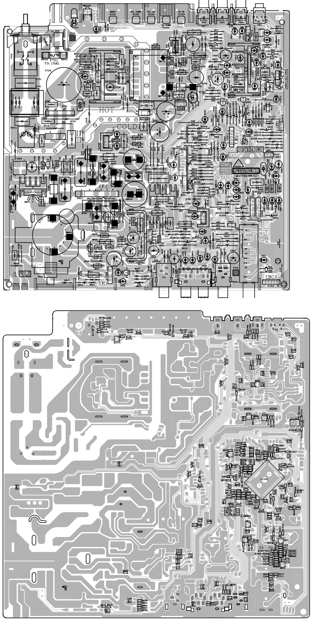
POWER BOARD PWB AND
SCHEMATIC


POWER AMPLIFIER
SCHEMATIC