Method for entering factory menu: Press MENU → [ -/--] → [9] → [1] → [8] one by one, then enter
factory menu, press the SLEEP button to select adjustment page, exit factory
menu to press the MENU button.
EEPROM initialization
Enter
the first page of factory menu, select “EEPROM INITIALIZE” to be “on”, after
turn off the unit, repeating turn on the unit is over.
White balance adjustment
Input
PAL signal of 16-level gray-scale (TIMING969 PATTAN921) from VG848 to AV
channel, enter user menu, set color to 0, APL to “off”, enter factory menu
white balance adjustment page, select color temperature, fixed the GGAIN to
50H, adjust BGIAN and RGAIN to 400nits, then the color coordinate to 284, 299.
Fixed the BOFFSET to 50H, adjust GOFFSET and ROFFSET to 5nits, then the color
coordinate to 284, 299.
Select cool tint, adjust color coordinate to 270, 283.
Select warm tint, adjust color coordinate to 313, 329.
Performance Inspections
1
TV function
Enter the search menu → auto search, connect RF-TV terminal to the central
signal source, check if there is station skipping.
2 AV/S input terminal
Input AV/S signal, check the picture and sound is normal
3 SCART terminal (note: check the SCART terminal, set display mode to AUTO)
3.1 Check SCART INPUT special function
3.1.1 SCART1 terminal function
a. After turn on the unit, connect the SCART1 to PM54200 signal generator, then
the unit auto select to SCART1 mode.
b. SCART signal generator sends CVBS signal to the unit, check if the image and
sound is normal.
It sends image format (16:9 and 4:3) to the unit, check if the unit auto
identify is normal. Change SCART signal to RGB signal, check if the image and
sound is normal, It sends image format (16:9 and 4:3) to the unit, check the
unit auto identify is normal. Select the PIP mode, connect earphone cable, and check
if the sound is normal.
3.1.2 SCART2 terminal function
a. After turn on the unit, connect the SCART2 to PM54200 signal generator, then
the unit auto select to SCART2 AV mode.
b. SCART signal generator sends CVBS signal to the unit, check if the image and
sound is normal.
It sends image format (16:9 and 4:3) to the unit, check if the unit auto
identify is normal, and display the SCART2 AV. Change SCART signal to Y/C
signal, select the SCART2 Y/C channel mode, check if the image and sound is
normal, It sends image format (16:9 and 4:3) to the unit, check if the unit
auto identify is normal. Select the PIP mode, connect earphone cable, and check
if the sound is normal.
3.2 Check SCART OUTPUT special function
3.2.1 SCART1 terminal function
Input signal in the TV states, connect the SCART1 terminal to the TV. Change
the TV program, check if output signal of SCART1 is TV signal, and the image
and sound is normal, change the unit
channel, the CART1 output TV signal, it can not other signal.
3.2.2 SCART2 terminal function.
Input signal in the TV/AV/S states, connect the SCART2 terminal to
the TV. Change the unit channel, check if output signal of SCART2 is current
signal, and the image and sound is normal.
6.4 YPbPr/YPbPr terminal
Input the YUV signal (VG-848 signal generator),
separate input YUV format signal of table 1, check if the image and sound is
normal. If the image is deflection of the H-field, select auto sync correction of
the SCREEN menu. If the image is slight disturb, adjust the FINE TUNE
correction of the SCREEN menu. Open the PIP mode, connect the earphone, and
check if the image and sound is normal.

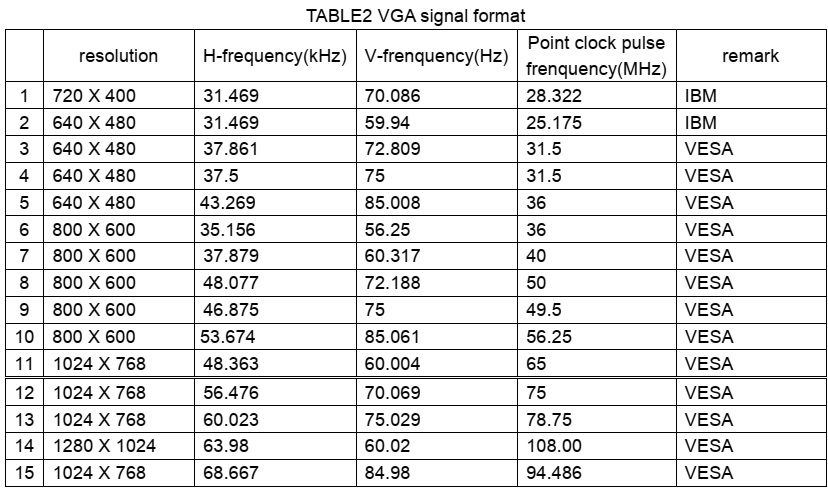
VGA terminal
Input the VGA signal (VG-848 signal generator),
separate input VGA format signal of table 1, check if the image and sound is
normal. If the image is deflection of the H-field, select auto sync correction of
the SCREEN menu. If the image is slight disturb, adjust the FINE TUNE
correction of the SCREEN menu. Open the PIP mode, connect the earphone, and
check if the image and sound is normal.
6.6 HDMI terminal
HDMI signal format receive the three high definition
signal: 480P, 576P, 720P/50/60 Hz, 1080I/50/60 Hz, except for the table 2
signal. Check if the image (contain HDCP ON and OFF) and sound is normal. If
the image is deflection of the H-field, select auto sync correction of the
SCREEN menu.
Open the PIP mode, connect the earphone, and check if
the image and sound is normal.


8.1 select TV channel
8.2 video menu, Mode: Standard, NR: Medium, APL:ON
8.3 sound menu, Volume: 20, Balance: 00, Equalizer:
Custom, HP Volume: 20;
8.4 edit menu, Color System: Auto, Sound System: DK;
8.5 option menu, Default Zoom: Auto, Child Lock: Off,
Menu Language: English, Country: UK,
WSS: OFF, Blue Screen: On.
Note: the 6.8.4 and 6.8.5 items should set according to
clients require.
Method of software upgrading
1.
Enter the software upgrading state of the TV
Method 1: press the VOL- button in the unit, turn on the main power switch,
then the screen display black screen, but the indicator to blue.
Method 2: Enter factory menu, select the IIC-BUS OFF item.
2. Connection upgrading tools with upgrading port.
3. Dual- click IAPWriter logo, enter the upgrading states (if the PC and the
IIC communication trouble, it can prompt.
4. Select the file menu
load the software follow as:
5. Select WRITE DEVICE
item of the device menu, till the right screen display “DONE”

Turn off the power ,
restart the unit.
Note: because of the software, it may be no-stabilization, the software can
auto download and write.
NOTE: Do not shut the power off or turn the TV set on during the
FLASH write. Otherwise it may lead to no way for flash to rewrite.

Working principle analysis of the unit
1.
Analog signal flow
Antenna reception signal send to integrative tuner (contain HF and IF amplifier
circuit), the tuner is controlled the command (SDA and SCL) of the MCU N301
(M16C), select appropriate channel to system switch, via HF amplifier and IF
amplifier decode, output video signal of 2VPP and sound signal of 1VPP.
Sound signal (SCART1, 2 sound, AV sound, YPbPr, HDMI and D-SUB) via N581
HEF4052BT (sound diverter switch) to output signal, it send to N801(MPS3410
sound processing and volume control) switch of audio. Select right/left sound
channel, their send to digital sound amplifier N803 (TPA3008) amplify, then
send to speaker.
After output video signal of tuner, SCART1 video signal and RGB signal via
matched resistance, the signal thought alone channel send to main decode
IC(N101 SVP-EX52) video switch, A/D transition, digital decode, image scale and
OSD superposition, then send to LVDS level drive for LCD screen.
AV, S-Video, SCART2 video and Y/C signal thought matched resistance, the signal
send to the N506 video switch (SN74CBT3257CDR), via switching to selected signal
(EX52_Y and EX52_C) to main decode IC (N101 SVP-EX52) video switch, A/D
transition, digital decode, image scale and OSD superposition, then send to
LVDS level drive for LCD screen.
D-sub and YPbPr signal thought matched resistance, the signal send to the N507
video switch (SN74CBT3257CDR), via switching to selected signal (EX52_YUV) to
main decode IC (N101 SVP-EX52) video switch, A/D transition, digital decode,
image scale and OSD superposition, then send to LVDS level drive for LCD
screen.
2. Digital signal flow:
HDMI signal thought HDMI reception chip N405 (SiI9011HDMI with HDCP function),
after receive, output digital format signal send to SVP-EX52 PIP channel
thought image scale and OSD superposition, then send to LVDS level drive for
LCD screen. The HDMI chip output audio digital format signal change to analog
sound signal from N403 (CS4344 audio DA transfer chip), then N581 switched to
N801 (MPS3410 sound processing and volume control).
3. TELETEXT function
This unit adopt main decode IC N101(SVP-EX52) of Trident company, it has
TELETEXT decode function, after decoded, the teletext information in OSD
display.
Sound
processing IC (MSP3410)
Sound
signal send to sound processing N801 MSP3410, and dual-circuit tuner has second
SIF, it sends to N801 (stereo decode and auto volume control), N801 has audio
channel switch, after switching in N581 (HEF4052BT), the audio input of
GA/HDMI/YPbPr will be sent to N801 together with the audio signal of TV and AV
to do the switching process. A way signal thought volume and high-low sound
controlled, output the left and right audio send to digital audio amplifier
N803 (TPA3008) amplify, then it send to speaker, other way signal output
left-right audio send to earphone amplifier N805 (NJW1109), after audio control
and power amplifier, it output to earphone socket. Other two ways signal output
audio of TV out and AV out by SCART terminal of video board.
Xoceco 27 inch and 32
inch power board [SMPS] schematic diagram

L32W5 SMPS schematic

