How
to take out the CD at emergency
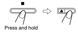
1. If power is
connected:
- Turn power
on.
- Open the
tray using the open/close key.
- Remove the
Door in the direction of arrow.
2. If power is
not connected:
- Turn the
gear clockwise using a screw driver as shown in Figure.
- Pull the
Tray in the direction of arrow @ and then remove the Door in the direction of
arrow.


Tuner
adjustment points

Cassette
deck adjustments
Test Equipment
needed
1.
Oscilloscope
2. VTVM
TAPE
1. MTT-111 (or
equivalent) : Test tape on which 3KHz signal is recorded (Tape speed
adjustment)
2. MTT-5512
(or equivalent)
3. MTT-113CN
(or equivalent) : Test tape on which 8KHz signal is recorded (Azimuth)
4. MTT-112B
(or equivalent) : Test tape on which 1KHz signal is recorded (L.R. channel
unbalance)
Adjustment
Procedure

Tracing
gain adjustment

Special
circuit descriptions
RF
Amp (KA9220) : NIC9220
RF I-V Amp(1)
and RF I-V Amp(2) currents are converted to voltage via internal resistance of
58k½ from the current of PD1(A+C) and PD2(B+D):
These voltage
are added by the RF summing amplifier. The signal (A+B+C+D) is applied to RFO
(No. 2 terminal).
RF output
voltage is calculated as follows :
VRF= -R3 x
(iPD1 + iPD2)
VRF= -R3 x
(V1/R1 + V2/R2)
VRF= -R3 x ( +
)
VRF= - x (V1 +
V2)
FOCUS
ERROR Amp(KA9220) : NIC9220
FOCUS ERROR
Amp amplifies the difference between RF I-V Amp(1) output (A+C) and RF I-V
Amp(2) output(B+D).
These two
signals are supplied to (-) and (+) input terminals of FOCUS ERROR Amp. The
FOCUS ERROR output is applied to FE (Terminal No.57).
The FE output
voltage of this low frequency component varies according to {(A+C) - (B+D)}.
VFE is
calculated as follows:
VFE = (R2/R1)
x (V2-V1) = 5.4(V2-V1)
This FOCUS
ERROR voltage is sent to FOCUS SERVO .
FOCUS
SERVO SYSTEM (KA9220) : NIC9220
When FS3 is
ON, high frequency gain decreases (time constant set by pin17, pin19 ;
capacitor is connected to internal resistance).
The capacitor
between pin 18 and GND sets the time constant to pass the low frequencies in
PLAY mode.
The maximum
frequency of the focus phase compensation is inversely proportional to the
resistance connected to pin 7. Focus search peak is about 1.1 Vp-p, and is
inversely proportional to the resistance connected to pins 22,23
(if this
resistance changes, the peak of track jump and sled kick change).
The inverted
input of FZC comparator is set to 5.7% of the difference between Vcc and
VC(pin69) {{5.7% x (Vcc-Vc)}.
Note : If the
resistance connected to pin7 changes, the phase compensation peak of the focus
tracking sled servos change. (The 'op-amp' dynamic range and offset voltage
also change.)

TRACKING
SLED SERVO SYSTEM (KA9220) : NIC9220
The capacitor
between pin 15 and 16 attenuates high frequencies when TG2 is off. The maximum
frequency of tracking phase compensation is inversely proportional to the
resistance connected to pin 7 (about 1.2kHz at 470k).
The tracking
jump (FWD and REV) is determined when TM3 and TM4 are ON, and the peak voltage
induced from the tracking coil is determined by both TM3 and TM4 currents and
the feed back resistance of pin 47.
Track jump max
voltage = TM3 (TM4) current x feedback resistance.
FWD or REV
sled kick occurs when TM5 or TM6 is ON, and the peak voltage added to sled
motor (determined by TM5 or TM6 current and the feedback resistance of pin 41.)
Sled jump max.
voltage = TM5(TM6) current x feedback resistance.
Each SW
current is determined by the resistance connected to pin 22 and 23.
When the
resistance is about 150½,
TM3 or TM4 =
11µA,
TM5 or TM6 =
22µA,
This current
is inversely proportional to the resistor, variable within a range of t 5 to 40
µA for TM3.
STOP is the
ON/OFF detection signal for the limit SW (or the sled motor's innermost circumference).

CD
Pack Exploded View

Schematic
diagram-Main board

Front
board schematic

CD
board schematic

Video
CD board schematic