COLOR
MONITOR LG Flatron 24M35H
service adjustments, schematic, EDID data, troubleshooting
North/Latin America,
Europe/Africa, Asia/Oceania
Take care during handling the LCD
module with backlight unit.
Must mount the module using
mounting holes arranged in four corners.
• Do not press on the panel, edge of the frame strongly or electric shock as
this will result in damage to the screen.
• Do not scratch or press on the panel with any sharp objects, such as pencil
or pen as this may result in damage to the panel.
• Protect the module from the ESD as it may damage the electronic circuit
(C-MOS).
• Make certain that treatment person’s body are grounded through wrist band.
• Do not leave the module in high temperature and in areas of high humidity for
a long time.
• The module not be exposed to the direct sunlight.
• Avoid contact with water as it may a short circuit within the module.
• If the surface of panel become dirty, please wipe it off with a soft material.
(Cleaning with a dirty or rough cloth may damage the panel.)
If you want to replace with the
new backlight (CCFL) or LIPS part, must disconnect the AC power because high
voltage appears at inverter circuit about 650Vrms.
Handle with care wires or
connectors of the inverter circuit. If the wires are pressed cause short and
may burn or take fire.
Adjustment
Apply to 58.4 cm (23 inch) Wide monitor made in
Monitor Factory Gumi Korea) or made in accordance with the standard of Gumi Factory
process.
Adjustment must be done as fixed
sequence, and adjustment sequence can be modified after agreement with the
responsible R&D engineer considering mass-production condition.
Power : AC 100 - 240 Voltage (Free)
Input signal:
RGB Input: As Product Standard (Signal ROM : LB800K Ver1.6)
RJ-45 input : As Product Standard (Ethernet connection through network from
Host PC)
* PC spec for MK(Minikey) Loader (TBD): CPU - Dual core 2.0 GHz UP, Memory - 2 GByte UP.
*PC spec for Host PC (TBD): CPU -
Dual core 2.0 GHz UP, Memory - 2 GByte UP.
Warm-up Time: Over than 30
minutes
Adjustment equipment : White balance equipment
(CA-110), Display adjust equipment, VG-813(or VG819), Oscilloscope, PC (More
than 486 computer ) & White balance adjust program.
Use factory automation equipment
and adjust automatic movement. But, do via passivity adjust in error
occurrence.
Board Assembly Line
15pin D-sub (RGB)
· Connect input signal to 15pin D-sub.
· Check the firmware version & model name. And write the firmware code to
the serial Flash ROM by ISP.
· Ready for adjustment : check whether adjustment command works normally or not
and the operating state of each mode.
· Check the display state of gray color when 256 gray scale patterns is
embodied.
· Read by EEPROM Read Command to check whether initial value is correct or not.
MK( Minikey ) Loading
· Open MK Loader Tool on MK Loader PC.
( * MK Loader PC should be connected Internet)
· Connect input signal to RJ-45 input with LAN cable connected network devices
such as routers.
· Turn on the Monitor set.
· Click the box when the ∞empty port ∞box is changed to “write mini-key” in MK
Loader Tool.
RJ-45 input
· Connect input signal to RJ-45 input with LAN cable connected network devices
such as routers.
· Check USB 1.1 Port (Keyboard/ Mouse) : @RJ-45 input
· Check USB 2.0 Port (USB Memory Stick 2port) : @RJ-45 input
· Check Audio (Ear-phone out/ Mic in/ Speaker) : @RJ-45 input,
PC audio volume : MAX
* LAN cable
* Router
* PC: vSpace S/W for N+ ( Ver 4.5.xx.xx ) --- Caution: Ver 4.4.xx.xx for N1742L
family
Total Assembly Line
· Ready : Heat-run during5 minutes in the state with signal
· Connect input signal to D-sub.
· Default value before adjustment : Contrast “70” , Brightness ‘100(Max)”
Adjustment of
Horizontal/Verticality screen position, Clock and Clock Phase at each Mode.
· There is no special factory mode adjustment. Writing initial value of EEPROM
in Board Assembly line is adjusting Preset Mode and Reset mode. (EEPROM is
initialized when AC Power is ON first.)
· If the change of FOS data is needed after M.P, it is possible by writing Mode
Data with EEPROM write command or modifying the Mode Data in MICOM itself.

Color coordinates adjustment and
Luminance adjustment.
Color coordinates adjustment
· Monitor Contrast / Brightness
- Contrast : 70
- Brightness : 100(Max)
· CA-110: Set “channel 9”
· Signal Generator : At cut-off and drive --> 16 step pattern for ADC
(Program No.: 31)
- Output Voltage : 700 mVp-p
- Output Mode : Mode 12 (SXGA 60 Hz)mode Setting.
Adjustment: Board Assembly Line
· Select RGB mode
· Input 16 step pattern for ADC (Program No.31 (Mode 12,Pattern 11)). (Video
level : 700 mVp-p)
· Adjust by commanding AUTO_COLOR_ADJUST
· Confirm “Success” message in Screen or Check the data of 0xFE, 0xFF address
of EEPROM(0XA6) is 0xAA after waiting 5 seconds.
· If there is “FAULT” message or the data of 0xFE, 0XFF address of EEPROM(0xA6)
is not 0xAA, do adjust again.
· If all Adjustment is completed, the values of 6500K, User Color and 9300K are
saved automatically.
· Select RGB mode
· Input 16 step pattern for ADC (Program No.31 (Mode
12,Pattern 11)). (Video level : 700mVp-p)
· Adjust by commanding AUTO_COLOR_ADJUST
· Confirm “Success” message in Screen or Check the data of 0xFE,0xFF address of
EEPROM(0xA6) is 0xAA after waiting 5 seconds.
Confirm at Total Assembly Line:
adjustment
· Check the data of 0xFE, 0xFF address of EEPROM(0xA6) is 0xAA.
· If the data of 0XFE, FF address of EEPROM(0xA6) is not 0xAA, do adjust again.
Confirm PRESET 6500K Color
coordinates and Adjust PRESET 9300K Color coordinates.
· Set as Aging mode ON, by commanding AGING_ON/OFF command code.
· Select Module that is being used in present production by commanding MODULE
SELECT. ( It is not needed so far. However, it will be needed to apply other
modules)
· Send SYSTEM RESET command to set Module data.
· Input Full White Pattern (Video level : 700 mVp-p)
· Set as 9300K by commanding COLOR_MODE_CHANGE Command code.
· Check to meet x = 0.283 ± 0.03, y=0.298 ± 0.03, and confirm.
· Only if it does not meet, adjust as below steps.
· Adjust to meet x = 0.283 ± 0.01, y=0.298 ± 0.01 in 5 minutes. And confirm.
· Save 9300K Color by commanding COLOR SAVE Command code.
· Set as 6500K by commanding COLOR_MODE_CHANGE
Command code.
Check to meet x = 0.313 ± 0.03,
y=0.329 ± 0.03, and confirm.
· Only if it does not meet, adjust as below steps.
· Adjust to meet x = 0.313 ± 0.01, y =0.329 ± 0.01, and confirm.
· Save 6500K Color by commanding COLOR SAVE Command code.
· Set as sRGB by commanding COLOR_MODE_CHANGE
Command code.
· Adjust to meet Y = 150 ± 50, and confirm.
· Save sRGB Color by commanding COLOR SAVE Command code.
Confirm User color coordinates.
· Confirm Whether User color is saved same as 6500K.
· After confirming Color coordinates, Must return to 6500K.
Operation state.
Confi Operation mode : Confirm
whether each appointed mode operate correctly or not.
Confirmation of Adjustment
condition and operation:
Confirm whether it meet Auto/Manual equipment Adjustment standard or not.
· Confirm Analog screen state : Confirm screen state at below mode.
Appointment mode (RGB input):
640*480 @60Hz (Mode 1),
800*600@75Hz(Mode 5),
1024*768@60Hz(Mode 8),
1280*1024@60Hz(Mode 12),
SMPTE pattern(Check 0%,5%,95%,100%)
–Mode can be added.
Confirm Auto adjustment
operation.
· Input Analog 1 Dot on/off & Rectangle Pattern at Mode 12(1280x1024@60 Hz)
· Confirm adjustment operation by changing Clock, Phase, H/V Position.
· Check Clock, Phase by pressing AUTO Key.
· Confirm first set of new lot by periods.
Other quality
· Confirm that each items satisfy under standard condition that was written
product spec.
· Confirm Applying Module & MICOM Setting --> Confirm with Service OSD
- Confirm at Service OSD by “Menu + Power key” on .(from Power
off)
- Confirm first set of new lot by periods, and confirm periodically when there
is Process change or Adjustment setting change.
OSD & Adjustment device Confirmation:
Confirm operation mentioned as
product spec.
· Vary Brightness and Contrast and confirm the variation of Luminance and
display status.
· Operate the f-engine function and confirm variation of Luminance.
· Make sure to do FACTORY RESET after confirmation of OSD function.
Confirm the display state by
inputting 8 color Bar Pattern & 256 Gray Scale pattern.
DPM operation confirmation: Check
if Power LED Color and Power Consumption operate as standard.
· Measurement Condition: 230 V@ 50 Hz (Analog)
· Confirm DPM operation at the state of screen without Video Signal.
RJ-45 input
· Connect input signal to RJ-45 input with LAN cable connected network devices
such as routers.
· Check USB 1.1 Port (Keyboard/ Mouse) : @RJ-45 input
· Check USB 2.0 Port (USB Memory Stick 2port) : @RJ-45 input
· Check Audio (Ear-phone out/Mic in/Speaker) : @RJ-45 input, PC audio volume :
MAX
* LAN cable
* Router
* PC: vSpace S/W for N+ ( Ver 4.5.xx.xx ) --- Caution: Ver 4.4.xx.xx for N1742L
family.
DDC EDID Write
( Set as Aging mode ON, by commanding AGING_ON/OFF command code. )
SUFFIX: xxxxxPN
· Connect analog Signal Cable to D-sub wafer.
· Write EDID DATA to EEPROM(24C08) by using DDC2AB protocol.
· Check whether written EDID data is correct or not.
> After writing EDID, send Elapsed Time Clear command. (Elapsed time should
not be displayed, after EDID writing)
: Confirm periodically (in the first set of new lot, process change)
whether module name and aging time disappeared on the self diagnostics OSD with
signal cable disconnected.
> If Elapsed Time Clear command isn’t executed, module name, aging time and
TCO word appear on the self-diagnostics OSD.(Module name and aging time should
not appear after writing EDID)
> Make sure to do FACTORY RESET at the final process.
Shipping
condition
Contrast : 70
|
Power Switch |
: Off |
|
Brightness |
: “100(Max)” |
|
Color Select |
: Preset (
6500K ) |
Language Select: Refer to product
spec.
OSD Position: Center
Power indicator: ON
Flatron f-engine : Normal
Standard of Auto/Manual equipment
adjustment

Pattern for Adjustment
Pattern 0 : FULL BLACK (State of
without video signal )
Pattern 1 : FULL WHITE (Don’t display other Character except for White Pattern)
Pattern 3 : FULL WHITE
Pattern 4 : Cross hatch pattern (Horizontal 10Line, Vertcial 8Line) &
Rectangle Pattern
Pattern 5 : 1 Dot on, 1 Dot off & Rectangle Pattern
Pattern 6 : Vertical Sync only input (Use signal cable of which Pin #5 is GND)
Pattern 7 : Horizontal Sync only input (Use signal cable of which Pin #5 is
GND)
Pattern 8 : State of without Vertical/Horizontal Sync and Video Signal. (Use
signal cable of which Pin #5 is GND)
Pattern 9 : 8 Color Bar Pattern + 16 Gray Level Pattern
Pattern 10 : SMPTE Pattern
Pattern 11 : 16 Gray Step Pattern (700mV)

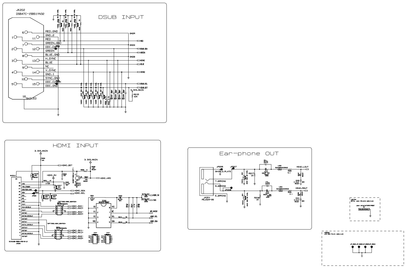
Schematic

Block Diagram

EDID data

Troubleshooting chart


