Friday, 3 January 2020

How to disassemble HP tablet - HP Pro Slate 8 Tablet – Step by step disassembling procedure – How to remove the case – how to replace the battery


HP Pro Slate 8 Tablet

How to remove Back cover
Before disassembling the tablet, follow these steps:
1. Turn on the tablet. If you are unsure whether the tablet is on, turn the tablet on, and then shut it down through the operating system.
2. Disconnect the power from the tablet by unplugging the power adapter cord from the tablet.
3. Disconnect all external devices from the tablet.
Remove the back cover:
1. Place the tablet on a Ưat surface, display panel side down, with the SD card slot and volume control buttons toward you.
2. Remove four Torx 4 screws (1) to release the bottom edge of the back cover (2) from the display panel assembly.
3. Remove the tape that secures the battery to the back cover (3), and then remove the cover (4).
How to remove Battery
Before removing the battery, follow these steps:
1. Turn on the tablet. If you are unsure whether the tablet is oƫ, turn the tablet on, and then shut it down through the operating system.
2. Disconnect the power from the tablet by unplugging the power adapter cord from the tablet.
3. Disconnect all external devices from the tablet.
4. Remove the back cover
Remove the battery:
1. Release the tape (1) holding the battery.
2. Disconnect the battery cable from the system board, and then remove the battery (2).
How to remove Rear-facing web camera
Before removing the rear-facing web camera, follow these steps:
1. Turn on the tablet. If you are unsure whether the tablet is to, turn the tablet on, and then shut it down through the operating system.
2. Disconnect the power from the tablet by unplugging the power adapter cord from the tablet.
3. Disconnect all external devices from the tablet.
4. Remove the back cover 
5. Remove the battery 
Remove the rear-facing web camera:
1. Remove the tape(1), and then release the ZIF connector (2) that secures the rear-facing web camera to the system board.
2. Remove the rear-facing web-camera (3) from the display panel assembly.
How to remove Front-facing web camera
Before removing the front-facing web camera, follow these steps:
1. Turn on the tablet. If you are unsure whether the tablet is on, turn the tablet on, and then shut it down through the operating system.
2. Disconnect the power from the tablet by unplugging the power adapter cord from the tablet.
3. Disconnect all external devices from the tablet.
4. Remove the back cover 
5. Remove the battery 
6. Remove the rear-facing web camera 
Remove the front-facing web camera:
1. Release the ZIF connector (1) that secures the front-facing web camera cable to the system board.
2. Remove the front-facing web camera (2) from the display panel assembly.
How to remove Top speaker
Before removing the top speaker and Wi-Fi auxiliary cable, follow these steps:
1. Turn on the tablet. If you are unsure whether the tablet is on, turn the tablet on, and then shut it down through the operating system.
2. Disconnect the power from the tablet by unplugging the power adapter cord from the tablet.
3. Disconnect all external devices from the tablet.
4. Remove the back cover 
5. Remove the battery 
6. Remove the rear-facing web camera 
7. Remove the front-facing web camera 
Remove the top speaker board:
1. Remove the foam pad (1) covering the top speaker board.
2. Disconnect the speaker (2) from the system board.
3. Disconnect the Wi-FI auxiliary cable (3) from the system board.
4. Detach the top speaker board (4) from the display panel assembly, and then remove the top speaker board and Wi-FI auxiliary cable.
How to remove LCM bracket
Before removing the LCM bracket and cable, follow these steps:
1. Turn on the tablet. If you are unsure whether the tablet is on, turn the tablet on, and then shut it down through the operating system.
2. Disconnect the power from the tablet by unplugging the power adapter cord from the tablet.
3. Disconnect all external devices from the tablet.
4. Remove the back cover 
5. Remove the battery
6. Remove the rear-facing web camera 
7. Remove the front-facing web camera 
8. Remove the top speaker 
9. Remove the antenna board 
Remove the LCM bracket and cable:
1. Remove one Torx 4 screw (1) that secures the LCM bracket to the system board, and then remove the LCM bracket (2).
2. Disconnect the LCM cable.

Thursday, 2 January 2020

Lenovo ThinkPad S3 – How to create and use recovery USB drive - Disassembling procedure – How to test the AC adapter

How to check the Power system 

To verify a power symptom, do the following:
1. Turn off the computer.
2. Connect the ac power adapter.
3. Turn on the computer. If the computer can be turned on, it means that either the battery pack or the ac power adapter is functional.
4. Insert a straightened paper clip into the emergency reset hole to reset the computer. If the computer is still powered on, it means that the ac power adapter is functional.
5. Turn off the computer.
6. Disconnect the ac power adapter and turn on the computer. If the computer can be turned on, it means that the battery pack is functional.
If you suspect a power problem, see the appropriate one of the following power supply checkouts:
“Checking the ac power adapter”
“Checking the built-in battery and operational charging”
“Checking the coin-cell battery”
Checking the ac power adapter
You are here because the computer fails only when the ac power adapter is used.
If the power problem occurs only when the docking station or the port replicator is used, replace the docking station or the port replicator.
If the system-status indicator does not blink three times when an ac power source is connected, check the power cord of the ac power adapter for correct continuity and installation.
To check the ac power adapter, do the following:
1. Unplug the ac power adapter cable from the computer.
2. Measure the output voltage at the plug of the ac power adapter cable. See the following illustration:
Note: Output voltage of pin 2 of the ac power adapter might differ from the one you are servicing.
3. If the voltage is not correct, replace the ac power adapter.
4. If the voltage is acceptable, replace the system board.
Note: Noise from the ac power adapter does not always indicate a defect.
Checking the built-in battery and operational charging
To check whether the battery charges properly during operation, do the following:
1. Discharge the battery until the remained battery power is less than 50%.
2. Connect the computer to ac power to charge the battery. If the battery status icon in the Windows notification area indicates that the battery is not charging, remove the battery and let it return to room temperature.
3. Reinstall the battery. If the battery is still not charging, replace the battery pack.
4. Check the battery status icon again. If the same error still exists, replace the system board.
Checking the coin-cell battery
To check the coin-cell battery, do the following:
1. Disconnect the battery connector.
2. Remove the coin-cell battery.
3. Measure the voltage of the coin-cell battery. See the following illustration.
If the voltage is correct, replace the system board.
If the voltage is not correct, replace the coin-cell battery.
If the coin-cell battery discharges quickly after replacement, replace the system board.


Creating and using a recovery USB drive
You can create a recovery USB drive as a backup for the Windows recovery programs. With the recovery USB drive, you can troubleshoot and fix the problems even if the preinstalled Windows recovery programs are damaged.
Creating a recovery USB drive
The USB drive that you use to create the recovery USB drive must be at least 16 GB of storage. The actual USB capacity that is required depends on the size of the recovery image.
Attention: The creation process deletes anything stored on the USB drive. To avoid data loss, make a backup copy of all the data that you want to keep.
To create a recovery USB drive, do the following:
Note: Ensure that your computer is connected to ac power during the following process.
1. Connect a proper USB drive (at least 16 GB of storage).
2. Type recovery in the search box on the task-bar. Then click Create a recovery drive.
3. Click Yes in the User Account Control window to allow the Recovery Media Creator program to start.
4. In the Recovery Drive window, follow the on-screen instructions to create a recovery USB drive.
Using the recovery USB drive
If you cannot start your computer, use the recovery USB drive to recover your computer.
To use a recovery USB drive, do the following:
Note: Ensure that your computer is connected to ac power.
1. Connect the recovery USB drive to the computer.
2. Turn on or restart the computer. Before the Windows operating system starts, repeatedly press the F12 key. The Boot Menu window opens.
3. Select the recovery USB drive as the boot device.
4. Select a preferred keyboard layout.
5. Click Troubleshoot to display the optional recovery solutions.
6. Select a corresponding recovery solution according to your situation. Then follow the instructions on the screen to complete the process.
DISASSEMBLING PROCEDURE 
How to remove the Keyboard
Remove the screws 1 that secure the keyboard.Push hard in the direction shown by the arrows 4 to unlatch the front edge of the keyboard (the edge that is close to you).
Note: Depending on the model, your computer might look different from the following illustration.
Pivot the keyboard slightly upward as shown by the arrow 5 . Then turn over the keyboard as shown by the arrow 6.
Note: Depending on the model, your computer might look different from the following illustration.
Detach the connectors and remove the keyboard.
How to remove Base cover assembly
Remove the screw caps 1 of the base cover assembly and the screw 2.
Loosen the rest of the screws that secure the base cover assembly.
Pry up the latches and then remove the base cover assembly.
Lenovo ThinkPadS3 – Disassembling procedure – How to test the AC adapter – How to test the Backup battery – How to remove the key board – How to remove the rare cover to replace battery.

Monday, 23 December 2019

How to enter to service mode AKAI LTA-32C902 troubleshooting and adjustments


AKAI LTA-32C902 - LTA-37C902 - SERVICE MODE AND ADJUSTMENTS 

Enter into factory menu
1. Enter into child lock of main menu in TV mode, press “OK, the password input box will appear;
2. Use remote control to input the follows in order: 7,red key, 9,blue key, then you can enter into factory mode menu. After entering into factory mode menu, sign of the factory menu M will appear.
NOTE:
1.if no especial demand, please do not enter into the 20 th P item(design mode);
2.when tuning the 16 th item ,the storage data will be cleaned off, therefore, if not necessary ,please do not adjust it, the items of index number 1,2,3,4,5,6 are not necessary to adjust.
Adjustment methods for factory menu
1. Select the adjusting item
You can skip to the adjusting items by pressing the number key, also can select the adjusting item in the order of P+/P-.when pressing the number key, if the adjusting item is 1~9,input the corresponding number keys and press down “OK”, if the adjusting items tens digit, input a tens digit. For example ,press number key 8 when adjusting the volume, you can see the color which become green, then press down “OK”, the color of index number turns red, So you already selected corresponding volume adjusting item.
If adjust DVD preset, first input 1,then input 3,you can adjust DVD preset.
2. Adjustment methods
Adjust it according to the operating key in above list. For one act operation ,press OK/V+.
example Auto Color, for some variable add/reduce, Example Volume, press V+/V- .
3. The illuminate of white balance and AutoColor adjustment method
Index 11 is corresponding to manual balance ,press “OK” or “V+” to display three corresponding variable, press “P+/P-”to select, press “V+/V-” to adjust, press down menu key to exit.
The index of AutoColor is 12,press “OK”or “V+” to do color revision, then the adjusted value will display.
4. BBE plus adjustment
Index number of BBE plus adjustment is 22 and 23,adjust it by adjusting “V+/V-”,the value of W270F8E
and W320F8E are set 0X09,but the W370F8E is set 0X0F.
5. Press down the DISPLAY first before switching the program number in factory mode, press P+/P- to switch before the display content do not disappear;
6. All menu functions are on in factory mode, if necessary you can use menu to check the items and effect test.
Factory debug item
1. Auto color revise( AutoColor)
Firstly finish auto color revise first before factory debug. Revise in TV,YPBPR and PC respectively.
Requisite Meter
PC - one
HD signal source – one
Debug(Revise in TV,YPBPR and PC respectively)
Park the channel in C-3 under TV mode TV, then do AutoColor.
Input color stripe signal in YPBPR and do AutoColor.
Input window signal in PC, the window is white, black signal around.
The result will appear in screen after AutoColor adjustment,make the adjustment results of Rgain Ggain and Bgain close to 0 × 80,if the difference is too great,adjust the value of HWUC_CON(auxiliary saturation),and readjust the AutoColor.
White balance, color temperature adjustment
1. Requisite Meter
CHROMA 7120 color analyze instrument( or same function instrument,contain color coordinate – chroma diversion card) one
White balance adjusting frock( request the video output range 0-1V is adjustable,750hm load)one
2. Prepare
A. connect all equipments, switch the condition of LCD TV to AV.
B. Set the picture of LCD TV for standard condition
C. Set the distance of light receiver of white balance from center place of LCD display screen for 15cm +/- 3cm .
D. Make sure that the environmental brightness is below 2cd/mP2P
3. White balance, color temperature adjustment
Before adjusting it, put the first LCD TV in AV condition, and the image in standard condition, white balance adjust frock send the white vertical signal output from video into AV, adjust output range of balance adjust frock, make the brightness of the LCD TV 200±20cd/mP2 P(use CHROMA 7120 color analyze instrument to obtain the brightness ),then fix the video output range of white balance adjust frock(until all the LCD TV are adjusted).
Enter into white balance adjusting item of factory mode, change R,G,B value(try best to adjust this 3 value biggest) .
Make color temperature coordinate value accord with that of the table below (error value within ±4%) :
SYMPTOMS AND CORRECTION
Symptom One:Display card of PC no image in DVI.
Reason and Resolve: If some display card of DVI can not receive the data when turning on the TV, there is no output; if pull out the DVI line abruptly, there is also no DVI output; Before starting PC, connect the DVI line with LCD TV steadily, So DVI can receive the correct date from DD ( Display Data Channel) when turning on the TV,DDC is in chassis 24LC21.
Symptom Two:No picture but sound, on LOGO when turning on the TV, background light is bright.
Reason and Resolve: Check the connect line in up screen, and connect the line.
Symptom Three: No picture,no sound ,no snowflake in TV mode, but AV is normal.
Reason and Resolve: Check the outside of high frequency (also bus and power supply), there is no problem ,but no output from high frequency, so the tuner is disabled.
Symptom Four:LCD TV can not be controlled.(inc red lamp is on but the TV is off, remote control and local keys can not control the TV ,etc.)
Reason and Resolve:the LCD TV can not work abruptly, power off and turning it on again.

Thursday, 19 December 2019

LG LCD TV Backlight blinking problem troubleshooting - LG 60LB7100 Intermittent Backlights


Backlights Blink
Backlights go OFF.
SMPS Trouble LED blinks 3 times then only 2 times.
Note: This panel was a Refurbished panel from parts.
Panel P/N: CRD31515701
TV ran for 4 days, 24 hours a day until symptom showed up.
The backlights would begin to blink. Usually 4 to 6 times then they would shut off completely.
SMPS LED was blinking 2 times indicating DC-to-DC converter problem.
However, when watching the SMPS trouble LED while the backlights were blinking, it blinked 3 times once or twice then it went to 2 times after the backlights went off. 3 times indicating Open LEDs.
While Backlights were blinking: Reading the test points EL50-EL54 EL62-EL67 on the SMPS for backlight grounding signals, all but two test points were reading approximately 4V. But two of them were reading 0V, (EL55 and EL64). Backlight Power was 70V.
While Backlights were off: Reading the test points EL50-EL54 EL62-EL67 on the SMPS for backlight grounding signals, all but two test points were reading approximately 7V.
But two of them were read 0V (EL55 d EL64). Backlight Power was 56V.
Note: In this model there are only 6 backlight drivers. So two test points are tied together per/driver.
Reading the test points EL50-EL54 EL62-EL67 on the SMPS for backlight grounding signals, all but two test points were reading approximately 6V. But two of them were reading 0V, (EL55 and EL64).
Note: In this model there are only 6 backlight drivers. So two test points are tied together per/driver.
Example: EL62 and EL54 are tied together, EL55, EL64 are tied together, etc
Note: When the Backlights are “off”, the reading are 2V on good LED bars and “0V” on the defective bar.
LED (LD701) would blink 3 times while backlights were blinking and 2 times after the backlights turned off.
Note: LED (LD701) blinking 3 times indicates an open backlight LED feedback line.
Check the Test points EL50-EL54 EL62-EL67 for “20V” volts. This would indicate an Open LED driver.
Using a 100 ohm resistor, one end to ground, touch the other end to the Test Point pin that has “20V”. If the backlight comes on, the panel is good, SMPS is bad.
After disassembling the panel, we found that the connector to the bottom LED Bar was intermittent. The connector is attached by simply pressing it down onto the connector. The Red wire (B+) to the bar was intermittent making contact with the connections on the LED Bar. On all “A” bars, LED B+ arrives on the (-) marked pin on the connector. On all “B” bars, LED B+ arrives on the (+) marked pin.
This connector is inserted by laying it over the connector on the board and pressing down to press it into place.  For those unable to do panel disassembly, panel replacement is necessary.
The best repair method for this would be to remove the wires and solder them directly to the LED bar.

Avoid solder bridges. Cut the crimped connector off the wire first.
For permanent fix, you should do this to all “outside” connectors on the right and the left side of the LED Bars.
Note: You may need to un-tape the wire harness to allow for slack. Be sure to re-tape after repair.
Examine each LED to make sure they have not become un-bonded. “Do not life by the LED lens”. Over time, this could cause overheating.
if they have, press down on either side of the LED for about 60 seconds to rebond.  Do not press down on LED.

Wednesday, 18 December 2019

How to disassemble BBKV3N,V3H,V5N,V5H pocket TV


All operations must be with strict anti-static measures. Operators must wear anti-static gloves or wrist ring; electric screwdriver must be grounded effectively and articles, such as nippers must be removed static before using Use cuspidal forceps to take out the LOCK button
Insert the forceps into the lock hole and then prize up one corner of the glass.
Use a slice with thickness about 0.1mm to in sert into the gap of the glass prized up and then peel off glue of the glass slowly to tale out the glass. Pay attention not to damage touch button FPC.
After peeling off glue of the glass, use nails to take out the glass.
Insert the 4 special slice clasp instruments into the relevant position of the 4 clasps.
Use the special hook tool, shown in the picture,to remove the middle casing.
Remove FPC flat cable clasp and then use forceps to take out FPC flat cable.
Use electric screwdriver or “+”-shaped screwdriver to take out 2 screws of main board.
Use iron to weld to separate the batter and buzzer lead wire on main board.
Take out main board components Take out battery components.
Take out the stainless steel cover board on rear side of display screen.
Take out display screen components from the direction shown in the picture.

Sunday, 15 December 2019

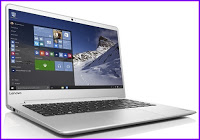
Lenovo laptop disassembling - Lenovo ideapad 710S – How to remove the battery pack – How to remove base cover


To verify a symptom, follow the steps below:
1. Turn off the computer.
2. Connect the AC adapter.
3. Make sure that power is supplied when you turn on the computer.
4. Turn off the computer.
5. Disconnect the AC adapter.
6. Make sure that the battery pack supplies power when you turn on the computer.
If you suspect a power problem, see the appropriate power supply checkout:
“Checking the AC adapter”
“Checking operational charging”
Checking the AC adapter
You are here because the computer fails only when the AC adapter is used.
If the power-on indicator does not turn on, check the power cord of the AC adapter for correct continuity and installation.
To check the AC adapter, follow the steps below:
1. Unplug the AC adapter cable from the computer.
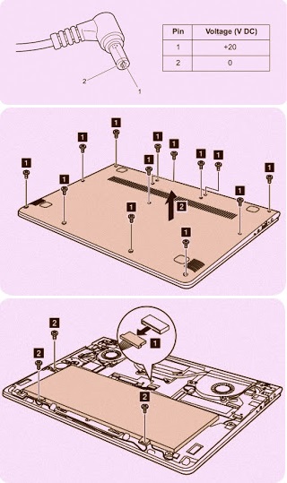
2. Measure the output voltage at the plug of the AC adapter cable. See the following figure:
Note: Output voltage for the AC adapter pin No. 2 may differ from the one you are servicing.
3. If the voltage is not correct, replace the AC adapter.
4. If the voltage is acceptable, do the following:
Replace the system board.
Note: Noise from the AC adapter does not always indicate a defect.
Checking operational charging
To check whether the battery charges properly during operation, use a discharged battery pack or a battery pack that has less than 50% of the total power remaining when installed in the computer.
Perform operational charging. If the battery status indicator or icon is not lit, remove the battery pack and let it return to room temperature. Reinstall the battery pack. If the charge indicator or icon is still off, replace the battery pack. If the charge indicator is still not lit, replace the system board.
Restore of factory default
The Lenovo ideapad 710S-13ISK computer comes with pre-installed OneKey Recovery System.In order to save application files and the initial backed up files of the system, the hard disk in a Lenovo computer includes a hidden partition when it is shipped. If you need to restore the system to the point of your first boot up, just enter Lenovo OneKey Recovery System and run System Recovery.
Disassembling procedure 
Base cover
Remove the rubber. Remove the screws 1. Then remove the base cover 2.
Battery pack
Disconnect the battery connector 1 and remove the screws 2.
Lift up and remove the battery.
PCI Express Mini Card for wireless LAN
Disconnect the two wireless LAN cables (black, white) 1, and then remove the screw 2.
Remove the card in the direction shown by arrow 3
In step 1, unplug the jacks by using the removal tool antenna RF connector (P/N: 08K7159), or pick up the connectors with your fingers and gently unplug them in the direction shown by the arrows.
Notes: The wireless LAN card has 2 cables in step 1. The wireless LAN card in some models might have 3 cables in step 1.

Wednesday, 11 December 2019

Lenovo Laptop disassembling – Lenovo ideapad 500S


How to test the AC Adapter Voltage – How to remove the LCD – How to remove the built in battery - Lenovo Laptop disassembling – Lenovo ideapad 500S
 To verify a symptom, follow the steps below:
1. Turn off the computer.
2. Connect the AC adapter.
3. Make sure that power is supplied when you turn on the computer.
4. Turn off the computer.
5. Disconnect the AC adapter.
6. Make sure that the battery pack supplies power when you turn on the computer.
If you suspect a power problem, see the appropriate power supply checkout:
“Checking the AC adapter”
“Checking operational charging” Checking the AC adapter
You are here because the computer fails only when the AC adapter is used.
If the power-on indicator does not turn on, check the power cord of the AC adapter for correct continuity and installation.
To check the AC adapter, follow the steps below

1. Unplug the AC adapter cable from the computer.
2. Measure the output voltage at the plug of the AC adapter cable. See the following figure:
Note: Output voltage for the AC adapter pin No. 2 may differ from the one you are servicing.
3. If the voltage is not correct, replace the AC adapter.
4. If the voltage is acceptable, do the following:
Replace the system board.
Note: Noise from the AC adapter does not always indicate a defect.
Checking operational charging
To check whether the battery charges properly during operation, use a discharged battery pack or a battery pack that has less than 50% of the total power remaining when installed in the computer.
Perform operational charging. If the battery status indicator or icon is not lit, remove the battery pack and let it return to room temperature. Reinstall the battery pack. If the charge indicator or icon is still off, replace the battery pack. If the charge indicator is still not lit, replace the system board.
Restore of factory default
The Lenovo ideapad 300S-14ISK/ideapad 500S-14ISK computer comes with pre-installed OneKey Recovery System.In order to save application files and the initial backed up files of the system, the hard disk in a Lenovo computer includes a hidden partition when it is shipped. If you need to restore the system to the point of your first boot up, just enter Lenovo OneKey Recovery System and run System Recovery.
Disassembling the laptop 
Base cover
Remove the screws 1. Then remove the base cover 2.
Battery pack
Detach IO board connector in the direction shown by arrows 1 and 2.
Unplug the battery connector 3 and remove the screws 4. Then remove the battery pack in the direction shown by arrow 5.
Hard disk drive
Remove the frame fixing screws 1.
Remove the hard disk drive in the direction shown by arrow 2
LCD unit
Remove the screws 1. Detach LCD connector in the direction shown by arrow 2.
Open the hinges 3, then remove the upper case from the LCD unit in the direction shown by arrow 4.

LG 52LG50FD, 52LG50FD-SA-Service adjustments-service mode entry-white balance adjustment-ADC component 1 RGB adjustment and more

  These adjustments are similar to 42LB7DF Because this is not a hot chassis, it is not necessary to use an isolation transformer. However...