Friday, 15 March 2019

HP EliteBook 820 G3 Notebook – Disassembling procedure – How to remove the battery – How to remove the – Bottom case – How to remove the HDD


HP EliteBook 820 G3 Notebook disassembling procedure 
How to remove Bottom cover
Before removing the bottom cover, follow these steps:
1. Turn off the computer. If you are unsure whether the computer is off or in Hibernation, turn the computer on, and then shut it down through the operating system.
2. Disconnect the power from the computer by unplugging the power cord from the computer.
3. Disconnect all external devices from the computer.
Remove the bottom cover:
1. Turn the computer upside down on a flat surface.
2. Remove the 11 rubber plugs (1) and the 11 Phillips PM2.5x5.0 screws beneath them (2) from the bottom cover.
Be sure to remove the screws in the following order.
3. Remove the SD card blank and the 1 PM2.0×7.0 screw beneath it (3) that secures the bottom cover to the computer.
4. Pry up on the top (near the display hinge) of the bottom cover to disengage it from the computer (4).
How to remove Battery
Before removing the battery, follow these steps:
1. Turn off the computer. If you are unsure whether the computer is off or in Hibernation, turn the computer on, and then shut it down through the operating system.
2. Disconnect the power from the computer by unplugging the power cord from the computer.
3. Disconnect all external devices from the computer.
4. Remove the bottom cover
To remove the battery:
Loosen the captive screw (1) and lift the tab to remove the battery from the computer (2).
How to remove Hard drive
Before removing the hard drive, follow these steps:
1. Shut down the computer. If you are unsure whether the computer is oƫ or in Hibernation, turn the computer on, and then shut it down through the operating system.
2. Disconnect all external devices connected to the computer.
3. Disconnect the power from the computer by ƭrst unplugging the power cord from the AC outlet, and then unplugging the AC adapter from the computer.
4. Remove the bottom cover
5. Remove the battery
To remove a hard drive:
1. Loosen the 4 captive screws (1) that secure the hard drive to the chassis.
2. Slide the hard drive (2) away from the center of the computer to disengage it from the connector.
3. Lift to remove the hard drive from the bay (3).
How to remove SSD
Before removing the SSD, follow these steps:
1. Turn oƫ the computer. If you are unsure whether the computer is oƫ or in Hibernation, turn the computer on, and then shut it down through the operating system.
2. Disconnect the power from the computer by unplugging the power cord from the computer.
3. Disconnect all external devices from the computer.
4. Remove the bottom cover
5. Disconnect the battery
Remove the SSD:
1. Remove the Phillips PM2.0×3.0 screw (1) that secures the drive to the system board.
2. Remove the drive (2) by pulling it away from the connector.
How to remove the Keyboard
Before removing the keyboard, follow these steps:
1. Shut down the computer. If you are unsure whether the computer is oƫ or in Hibernation, turn the computer on, and then shut it down through the operating system.
2. Disconnect all external devices connected to the computer.
3. Disconnect the power from the computer by ƭrst unplugging the power cord from the AC outlet, and then unplugging the AC adapter from the computer.
4. Remove the bottom cover
5. Remove the battery
Remove the keyboard:
1. Remove the 2 Phillips PM2.5×3.0 screws that secure the keyboard to the computer (1).
2. Position the computer upright with the front toward you.
3. Open the computer as far as possible.
4. Insert a screwdriver or similar thin tool into the hole beside the heat sink/fan assembly, and then press on the back of the keyboard until it disengages from the computer (2). Rotate the top of the keyboard upward, and then lift the keyboard up at an angle to disengage the tabs at the bottom of the keyboard.
5. Slide the keyboard slightly downward toward the palm rest to disengage the top of the keyboard from the top cover (1). Remove the pointing stick cable (2), the keyboard backlight cable (3), and the keyboard cable (4).
6. Remove the keyboard (5).

Samsung Galaxy tab GT-P7500 - Troubleshooting procedure - Power on problem and troubleshooting - Battery Charging problem


Samsung Galaxy  GT-P7500 troubleshooting 
Abnormal charging part
Check C514 whether voltage reading is greater than 5V
Check the TA and the DLC (TA or DLC may not be connected properly)
Check C510 whether voltage reading is greater than 5V
Check U507 chip (U507_OVP chip may not work)
Check C749 whether voltage reading is greater than 4.2V
Check U704 chip (U704 chip may not work at room temperature)
Check battery voltage is change when TA is connected
Check U704 chip (U704 chip may not work)
Check C743 whether voltage is change when TA is connected
Check U704 chip (U704 chip may not work)
Microphone Part
Check main microphone function
in voice call receiver mode
Check the voltage at
C406 = 2.8V
Resolder or replace U404
Check component soldering
statuses of C426, C427
Resolder or replace C426, C427
Speaker Part
Check the signals on R427,R428,R338, R338
Resolder or replace U404
Replace the speaker module
BT/WIFI
BT/WiFi is not working
Check BT or WiFi function
Enable BT or WiFi Function
Check the Voltage on C260 = 1.8V
Check AP PMIC(U703)
Check 37.4MHz Clock at R213
Check OSC202
Check the Voltage on L214 = 1.5V
Resolder or change L214
Check the Status of C282, ANT202
Resolder or Replace C282, ANT202
Resolder or Replace U204
Power On does not work
Check "Power on" by power cable with jig-on
Check the switch circuit, FET gate voltage, FET voltage
Check the 30pin to 50pin FPCB(SLC500), Wrong assembly or Wrong connection.
Check the Battery Voltage is more than 3.6V
Charge the Battery (Battery power is low)
Check U703(PMIC) and Power on voltage(C727≥1.2V, C734 ≥1.2V, C730≥1.8V, C725≥ 1.8V, C728≥1.1V, C723≥3.3V, C720≥2.85V)
Check U703. Change the problem point. (short, open, crack, etc.)
If PMIC has problem, change U703
Check U702(_RESET). this pin has to go high level(about 2V),and to go low level after 480ms
Check U6006(A1,Y1). If you push the power on button ,, A1,Y1 has to go high level.
Check the Clock at OSC700(C718) that frequency is 32K
Check the clock generation circuit (related to OSC700)
check the initial operation
TSP
Touch Screen does not work
Check TSP Connector on Main PBA
Reconnect the SLC1000
U1004 Pin64 = 3.3V(C1033) and Pin8 = 1.8V(C1029)
Resolder or Replace U1004 U1001,1002,1003 Pin A1 = 3.3V(C1000,C1006,C1012)
Resolder or Replace U1001,1002,1003
Check the I2C signal of
Sensor IC(R6050, R6051)
Resolder R6050, R6051
Replace TSP Module
3 MEGA PIX CAM
"Camera" function does not work
Check the Camera connector on Main PBA
Reconnect the HDC900
Check the voltage
C902 = 1.2V
C901 = 2.8V
C913 = 1.8V
C900 = 1.8V
Resolder U900,R900,R902,L900
Resolder U901
Resolder U902
Replace the PBA
Check R903 is 24MHz
Resolder R903 Replace the PBA
Check the I2C line TP902 & TP903 = HIGH
Resolder R6044, R6045 Replace the PBA
Check F900 is OK
Resolder F900 Replace the PBA
Replace the camera module
Initial Failure
CP_RST(R320), PDA_ACTIVE(R6067) >= 1.8V(HIGH)
Check UCP6000 (short, crack, etc.)
CP_ON(TP_CP_ON), PHONE_ACTIVE(TP6024)>= 1.8V(HIGH)
Check UCP300 (short, crack, etc.)
AP_nRST(U703_pin #G8,TP702) "low -> high"?
Replace OSC 300 and OSC700
There are 26MHz wave forms at OSC600(C6082) and 26MHz wave forms at OSC100(C150)
Replace OSC600 and OSC100
LCD display OK?
Check the LCD part(short, crack, etc.)
Sound is OK?
Check the Audio Part(short, crack, etc.)
LCD
LCD is still off after PWR ON
Check the connection of SLC800
Reconnect the SLC800
Check the C818 and High(18V)
Check the Backlight Driver IC(U805)
Check C821 = 1.8V, C823 = 3.3V, C833= 1.2V
Check the LDO(802) DC-DC(U803) DC-DC(U804)
Check the signal DISPLAY_PCLK(TP809) LCD_D(0)(TP801)
Check the IC UCP6000
Check the signal IDISPLAY_PCLK(TP806) LCD_F(0)(TP800)
Check the freq of C813(19.2MHz)
Replace or resolder OSC800
Check the U801
Check C800 = 1.8V, C801 = 3.3V
Check the IC U800
Replace LCD Module

HP Pavilion 11 X2 – dissembling procedure – How to remove the display – How to remove the RTC battery


Disassembling procedure 
How to remove Display enclosure
Before disassembling the tablet, follow these steps:
1. Turn off the tablet. If you are unsure whether the tablet is off or in Hibernation, turn the tablet on, and then shut it down through the operating system.
2. Disconnect the power from the tablet by unplugging the power cord from the tablet.
3. Disconnect all external devices from the tablet.
Remove the display enclosure:
1. Place the tablet on a flat work surface, with the display screen facing down and the rear-facing webcamera toward you.
2. Lift up on the top edge of the display enclosure (1) until the tabs built into the enclosure release from the display panel assembly.
3. Remove the display enclosure (2) from the tablet
How to remove Sensor board
Before removing the sensor board, follow these steps:
1. Turn off the tablet. If you are unsure whether the tablet is off or in Hibernation, turn the tablet on, and then shut it down through the operating system.
2. Disconnect the power from the tablet by unplugging the power cord from the tablet.
3. Disconnect all external devices from the tablet.
4. Remove the display enclosure
Remove the sensor board:
1. Disconnect the tablet battery cable from the system board.
2. Disconnect the sensor board cable (1) from the system board.
3. Disconnect the power button board cable (2) from the sensor board.
4. Detach the sensor board (3) from the display panel assembly. (The sensor board is attached to the display panel assembly with double-sided tape.)
5. Remove the sensor board.
Reverse this procedure to install the sensor board.
How to remove Wireless antenna
Before removing the wireless antenna, follow these steps:
1. Turn off the tablet. If you are unsure whether the tablet is off or in Hibernation, turn the tablet on, and then shut it down through the operating system.
2. Disconnect the power from the tablet by unplugging the power cord from the tablet.
3. Disconnect all external devices from the tablet.
4. Remove the display enclosure
5. Disconnect the tablet battery cable from the system board
Remove the wireless antenna
1. Disconnect the WLAN antenna cables (1) from the terminals on the WLAN module.
2. Release the wireless antenna cables from the routing clips (2) built into the display panel assembly.
3. Detach the wireless antenna transceivers (3) from the heat sink. (The wireless antenna
transceiver is attached to the heat sink with double-sided tape.)
4. Remove the wireless antenna cables and transceivers. Reverse this procedure to install the wireless antenna cables and transceivers.
How to remove Front-facing web camera
Before removing the front-facing web camera, follow these steps:
1. Turn off the tablet. If you are unsure whether the tablet is off or in Hibernation, turn the tablet on, and then shut it down through the operating system.
2. Disconnect the power from the tablet by unplugging the power cord from the tablet.
3. Disconnect all external devices from the tablet.
4. Remove the display enclosure
5. Disconnect the tablet battery cable from the system board
Remove the front-facing web camera:
1. Release the ZIF connector (1) to which the front-facing web camera cable is attached, and then disconnect the front-facing web camera cable from the system board.
2. Remove the Phillips PM1.85×1.60 screw (2) that secures the front-facing web camera bracket to the display panel assembly.
3. Swing the right side of the bracket (3) up and to the left until the bracket releases from the tab
(4) built into the display panel assembly.
4. Remove the front-facing web camera (5).
How to remove RTC battery
Before removing the RTC battery, follow these steps:
1. Turn off the tablet. If you are unsure whether the tablet is off or in Hibernation, turn the tablet on, and then shut it down through the operating system.
2. Disconnect the power from the tablet by unplugging the power cord from the tablet.
3. Disconnect all external devices from the tablet.
4. Remove the display enclosure
5. Disconnect the tablet battery cable from the system board
Remove the RTC battery:
1. Disconnect the RTC battery cable (1) from the system board.
2. Detach the RTC battery (2) from the display panel assembly. (The RTC battery is attached to the display panel assembly with double-sided tape.)

Friday, 15 February 2019

How to replace the battery of Apple iPhone – Apple iPhone 3GS Removal and replacement


Apple iPhone 3GS: Step by Step battery replacement procedure 
Remove the two 3.7mm Phillips #00 screws from the dock-connector end of the iPhone.
Remove the metal handle from the suction cup. It's easier and safer to grip the suction cup's base instead of the metal handle. Be very careful when opening the iPhone so that the cables under the display are not severed. There is a rubber gasket between the silver front bezel and black display assembly. A bit of force is required in this step to separate the iPhone's display assembly. It may help to rock the suction cup back and forth to remove the display assembly. Use a small suction cup near the Home button to gently pull up the bottom portion of the iPhone's display assembly. If the display assembly is too damaged to allow the suction cup to adhere, tape with a strong adhesive such as duct tape or packing tape may be used.
The display assembly is still connected to the iPhone by several cables, so don't try to remove it entirely just yet. Rotate the display assembly up until it is at an angle of approximately 45 degrees.
Continue to hold the display assembly with one hand, and use your other hand and a spudger to disconnect the black ribbon cable labeled "1". (Cable 1 is for the display)
Be careful to insert the spudger from the left, as shown in the picture (UNDER THE RIBBON). If you try to pry up the ribbon from the right, you could damage the ribbon connector and need to replace the display!
Al l connectors except the ribbon connector mentioned in step 7 release upwards.
Rotate the display assembly up until it is roughly vertical. This will allow easier access for disconnecting the remaining cables. Use a spudger to disconnect the black ribbon cable labeled "2". (Cable 2 is for the capacitative touch panel)
Please note: You may find on some non-American (Chinese, European) versions of the 3G that the flip up plastic tab does not exist. In this case you would slide the ribbon cable towards the screen until it is removed. When you assemble it, you would apply pressure to the ribbon to insert it back into the ribbon "socket." Some iPhones may have the connector colors reversed (black plastic tab, white connector) for connector "3". Make sure you're flipping up the tab properly, otherwise you may damage the connector. Use a spudger to flip up the white plastic tab holding the ribbon cable "3" in place. The white tab will rotate up 90 degrees, releasing the ribbon cable. Slide the black ribbon cable out of its connector, and remove the display assembly from the iPhone.
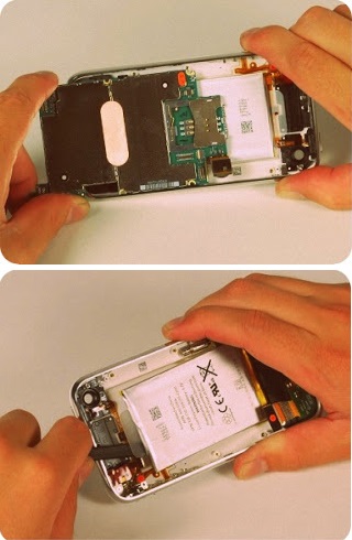
Insert your SIM eject tool or a paper clip into the hole next to the headphone jack. Press down on the tool until the SIM card tray pops out. Grasp the SIM card tray and slide it out of the iPhone. Use a spudger to disconnect the ribbon cable labeled "4."
Use a spudger to disconnect the ribbon cable labeled "5."
Use a spudger to disconnect the ribbon cable labeled "6." If you have an iPhone 3GS, refer to the second picture and use a spudger to disconnect the ribbon cable labeled "7." Be certain that the connectors on the ribbon cables are perfectly aligned with the sockets on the mother board before applying pressure. This may require a magnifying glass or jewelers' loupe.
Remove the following 8 screws: Five 2.3 mm Phillips #00 screws with partial threads securing the logic board to the rear case.
Two 2.3 mm Phillips #00 screws with full threads securing the logic board and camera.
One 2.9 mm Phillips #00 screw from beneath the "Do not remove" sticker.
N ote for re-assembly: The screw that goes next to the camera (bottom right orange highlighted screw) also has a metal strip that holds the camera in place.
Remember to put this strip back in place before you insert the 2.3 mm Phillips #00 screws with full thread next to the camera
Use a spudger to gently pry the camera up and out of its housing in the rear case. The camera cannot be removed entirely yet because it's connected to the bottom of the logic board. Use a spudger to gently pry up the end of the logic board closest to the dock connector. There is a small golden grounding tab on logic board adjacent to the 'do not remove sticker'. Be VERY careful this does not snag on the side of the case when prying up the logic board; it breaks easily. If you have signal problems after removing the logic board, check this ground tab. If the board won't lift up, double check to make sure all the screws securing the logic board have been removed.
Slide the logic board towards the dock connector and out of the iPhone. When replacing the logic board after installing battery, connect the camera to the logic board before inserting it into the case. Then make sure to set the top section of the logic board (where the SIM tray is) in place before settling the rest of the board in place. This is important, as sometimes the SIM card slot will not align into place. Once the top section is in place, the bottom section can be maneuvered into place. You will know the logic board is correctly installed when the SIM tray is aligned with the opening in the iPhone case and the camera module seats neatly into its place.
Use a spudger to pry the battery up from the rear case. The battery is attached with an adhesive strip around the perimeter of the battery. To prevent the battery from bending during the removal process, we recommend against using just the plastic pull-tab . *Note: Removing the battery is NOT necessary for replacing the GPS antenna. It merely gives you more space for removing the headphone assembly (which is also unnecessary to completely remove). The iPhone's battery is attached to the rear case with a mild adhesive. This adhesive usually comes out attached to the battery. If your replacement battery already includes an adhesive backing, you're all set. If your replacement battery doesn't have an adhesive backing, you'll want to transfer the adhesive from your old battery to the new one.
You can use a hair dryer or heat gun on its lowest setting to heat the back of the case. This will help loosen the adhesive bond before using the spudger to separate the battery from the case back.

Tuesday, 5 February 2019

How to calibrate Vela ventilator


Operational Verification and Calibration
Prior to using the Vela ventilator on a new patient the following checks should be carried out to ensure optimum performance. Verification testing should always be performed “off patient”.
Note: If any portion of the following performance check fails, and you are unable to correct the problem, contact your VIASYS Healthcare Certified Service Technician.
First perform the User Verification Tests (UVTs). To access the UVTs, do the following’
1. After disconnecting the patient, turn the ventilator OFF (i.e., STANDBY).
2. Press and hold the Accept button.
3. While holding the Accept button, turn the ventilator ON. Continue to hold the button until the ventilator completes the Power On Self Tests (POST).
4. Release the Accept button when the UVT menu appears in the screen. The Audible Alarm sounds. Press Alarm Reset button to clear.
5. Press the Patient Removed touch screen icon, the UVT test selection screen displays.
6. Press the appropriate touch screen icon to begin a test.
Lamp Test
Run this test to check the front lamps to make sure they are functioning properly.
1. Press the LampTest touch screen icon to start the test. The ventilator illuminates all front panel LEDs.
2. Press the LampTest touch screen icon again to turn the LEDs off and exit the test.
Switch Test
Run this test to check the front panel membrane switches to make sure they are working properly.
1. Press the SWITCH TEST icon.
2. Press each membrane switch control in turn. Watch for the name of the control to appear in the message bar at the bottom left of the touch screen as follows:
3. Press the SWITCH TEST icon again to exit the test.
Alarm Test
Run this test to check the audible alarm.
1. Press the Alarm Test touch screen icon to start the test. The audible alarm sounds.
2. Press the Alarm Test touch screen icon again to silence the audible alarm and exit the test.
Filter Test
Run this test to check the differential pressure across the turbine inlet filter. A high differential pressure may indicate a dirty or occluded filter.
1. Press the Filter Test touch screen icon. The turbine accelerates flow to 140 lpm and checks the differential pressure to make sure it is within range. At the end of the test, the ventilator displays a pass or fail message. If the test passes, the following message appears:
x.x Passed
where x.x is the average turbine differential pressure and P indicates the test passed. If the test fails, the following message appears:
x.x Failed
where x.x is the average turbine differential pressure and F indicates the test failed:
2. If the test fails, check the rotation of the turbine inlet filter to make sure that the seam is horizontally oriented and run the test again. If the test fails again, contact a Bird Certified Service Technician.
Leak Test
Note:This test should be performed with all circuit accessories installed (e.g., humidifier, water traps, and so on.) Make sure al connections are secure and all openings occluded before beginning the test.
Run this test to make sure the patient breathing circuit is not leaking.
1. Attach a one-liter test lung (P/N 33754) at the patient breathing circuit wye.
2. Press the Leak Test touch screen icon to run the test. The test begins by increasing the pressure in the patient breathing circuit to 60 cmH2O. The ventilator then displays the following messages in sequence:
Leak test requested
Leak test in progress
3. The ventilator then waits 10 seconds and measures the circuit pressure again. If the difference between the starting and ending measurements is less than or equal to 6 cmH2O, the test passes and the ventilator displays the following message:
xx.x Passed
where xx.x is the ending measurement.
4. Otherwise, if the difference is more than 6 cmH2O, the test fails and the ventilator displays the following message:
xx.x Failed
5. If the test fails, check all connections to make sure there are no leaks and repeat the test.
Exit
To exit the UVTs press the EXIT touch screen icon.

HP ENVY 8 Note 5000 Tablet – Disassembling procedure


HP ENVY 8 Note 5000 Tablet – Disassembling procedure – How to remove the back cover – how to remove the battery – How to remove the frame
How to remove White back cover
Before removing the white back cover, follow these steps:
1. Turn off the tablet. If you are unsure whether the tablet is off, turn the tablet on, and then shut it down through the operating system.
2. Disconnect the power from the tablet by unplugging the power adapter cord from the tablet.
3. Disconnect all external devices from the tablet.
Remove the white back cover:
1. Place the tablet on a flat surface, display panel side down.
2. Insert a thin tool (2) at the bottom right edge of the white cover, and use the tool to release the cover from the clips and adhesive holding it to the tablet.
3. Lift the cover (3) away from the tablet.
How to remove Black back cover
Before removing the black back cover, follow these steps:
1. Turn off the tablet. If you are unsure whether the tablet is off turn the tablet on, and then shut it down through the operating system.
2. Disconnect the power from the tablet by unplugging the power adapter cord from the tablet.
3. Disconnect all external devices from the tablet.
4. Remove the white back cover
Remove the black back cover:
1. Place the tablet on a flat surface, display panel side down
2. Using a heat gun, gently heat a small portion the black back cover to loosen the adhesive. Keep the heat away from the camera.
3. Insert a thin tool (1) at the inside edge of the black cover.
4. Lift the cover (2) and peel to remove.
How to remove Middle frame
Before removing the middle frame, follow these steps
1. Turn off the tablet. If you are unsure whether the tablet is off  turn the tablet on, and then shut it down through the operating system.
2. Disconnect the power from the tablet by unplugging the power adapter cord from the tablet.
3. Disconnect all external devices from the tablet.
4. Remove the following components:
a. Micro SIM/microSD card tray
b. White back cover
c. Black back cover
Remove the middle frame:
1. Place the tablet on a flat surface, display panel side down.
2. Remove the 4 larger 4 mm P0 Phillips head screws from the middle frame.
3. Remove the remaining fourteen 2 mm P0 Phillips head screws that secure the middle frame to the tablet.
4. Insert a thin tool (1) where the display is connected to the frame, and then slide the tool around the frame to separate the frame from the display.
5. Remove the frame (2).
How to remove Side key buttons
Before removing the side key buttons, follow these steps:
1. Turn off the tablet. If you are unsure whether the tablet is off turn the tablet on, and then shut it down through the operating system.
2. Disconnect the power from the tablet by unplugging the power adapter cord from the tablet.
3. Disconnect all external devices from the tablet.
4. Remove the following components:
a. Micro SIM/microSD card tray
b. White back cover
c. Black back cover
d. Middle frame
Remove the side key buttons:
1. Place the tablet on a flat surface, display panel side down.
2. Push in on the side key buttons, and then remove the button tray up away from the tablet.
How to remove Battery
Before removing the battery, follow these steps:
1. Turn off  the tablet. If you are unsure whether the tablet is off turn the tablet on, and then shut it down through the operating system.
2. Disconnect the power from the tablet by unplugging the power adapter cord from the tablet.
3. Disconnect all external devices from the tablet.
4. Remove the following components:
a. Micro SIM/microSD card tray
b. White back cover
c. Black back cover
d. Middle frame
Remove the battery:
1. Lift the black plastic thermal pad (1) up and away from the battery.
2. Disconnect the battery cable (2) from the system board.
3. Grasp the pull-tab on one of the 3 strips of tape and then carefully and slowly pull straight away, parallel with the tablet, until the entire strip has been removed. After releasing the 3 stretch-release tapes, carefully remove the battery (3) from the tablet.

Sunday, 13 January 2019

HP Chromebook 14 – Disassembling procedure


Disassembling procedure – How to remove the key board – How to remove the Battery – How to detach the display unit - HP Chromebook 14
HP Chromebook 14: disassembling procedure 
How to remove Keyboard/top cover
Before removing the disassembling the computer, follow these steps:
1. Turn off the computer. If you are unsure whether the computer is off or in Hibernation, turn the computer on, and then shut it down through the operating system.
2. Disconnect the power from the computer by unplugging the power cord from the computer.
3. Disconnect all external devices from the computer.
Remove the keyboard/top cover:
1. Close the computer.
2. Turn the computer upside down, with the front toward you.
3. Remove the thirteen Phillips PM2.5×6.5 screws that secure the keyboard/top cover to
the computer.
4. Lift the front end of the keyboard/top cover (1) and swing it up and back until the left and right edges detach from the base enclosure.
5. Lift the keyboard/top cover (2) until the back edge detaches from the base enclosure.
6. Slide the keyboard/top cover (3) forward until the keyboard and TouchPad ribbon cables
are accessible
7. Release the zero insertion force (ZIF) connector (1) to which the keyboard cable is attached, and then disconnect the keyboard cable (2) from the system board.
8. Release the ZIF connector (3) to which the TouchPad cable is attached, and then disconnect the TouchPad cable (4) from the system board.
How to remove Battery
Before removing the battery, follow these steps:
1. Turn off the computer. If you are unsure whether the computer is off or in Hibernation, turn the computer on, and then shut it down through the operating system.
2. Disconnect the power from the computer by unplugging the power cord from the computer.
3. Disconnect all external devices from the computer.
4. Remove the keyboard/top cover
5. Remove the speakers
Remove the battery:
1. Disconnect the battery cable from the system board.
2. Remove the Phillips PM2.5×4.5 screw (1) that secures the battery to the base enclosure.
3. Lift the left side of the battery (2) until the battery is clear of the alignment post (3) in the middle of the battery.
4. Release the battery (4) by sliding it to the left.
5. Remove the battery (5) by sliding it forward.
How to remove Display assembly
Before removing the display assembly, follow these steps:
1. Turn off the computer. If you are unsure whether the computer is off or in Hibernation, turn the computer on, and then shut it down through the operating system.
2. Disconnect the power from the computer by unplugging the power cord from the computer.
3. Disconnect all external devices from the computer.
4. Remove the keyboard/top cover
5. Disconnect the battery cable from the system board
Remove the display assembly:
1. Disconnect the display panel cable (1) from the system board.
2. Disconnect the WLAN antenna cables (2) from the terminals on the WLAN module.
3. Release the WLAN antenna cables from the routing channel (3) built into the base enclosure.
4. Disconnect the WWAN antenna cables (4) from the terminals on the WWAN module.
5. Release the WWAN antenna cables from the routing channel (5) built into the base enclosure.
6. Remove the two Phillips PM2.5×5.5 screws (1) that secure the display assembly to the
base enclosure.
7. Remove the display assembly (2).

LG 52LG50FD, 52LG50FD-SA-Service adjustments-service mode entry-white balance adjustment-ADC component 1 RGB adjustment and more

  These adjustments are similar to 42LB7DF Because this is not a hot chassis, it is not necessary to use an isolation transformer. However...