Tuesday, 17 August 2021

Xoceco 27 inch and 32 inch LCD TV – How to enter the service mode, service mode adjustments, SMPS (Power board) schematics software update procedure


Method for entering factory menu: Press MENU → [ -/--] → [9] → [1] → [8] one by one, then enter factory menu, press the SLEEP button to select adjustment page, exit factory menu to press the MENU button.

EEPROM initialization
Enter the first page of factory menu, select “EEPROM INITIALIZE” to be “on”, after turn off the unit, repeating turn on the unit is over.
White balance adjustment
Input PAL signal of 16-level gray-scale (TIMING969 PATTAN921) from VG848 to AV channel, enter user menu, set color to 0, APL to “off”, enter factory menu white balance adjustment page, select color temperature, fixed the GGAIN to 50H, adjust BGIAN and RGAIN to 400nits, then the color coordinate to 284, 299. Fixed the BOFFSET to 50H, adjust GOFFSET and ROFFSET to 5nits, then the color coordinate to 284, 299.
Select cool tint, adjust color coordinate to 270, 283.
Select warm tint, adjust color coordinate to 313, 329.
Performance Inspections
1 TV function
Enter the search menu → auto search, connect RF-TV terminal to the central signal source, check if there is station skipping.
2 AV/S input terminal
Input AV/S signal, check the picture and sound is normal
3 SCART terminal (note: check the SCART terminal, set display mode to AUTO)
3.1 Check SCART INPUT special function
3.1.1 SCART1 terminal function
a. After turn on the unit, connect the SCART1 to PM54200 signal generator, then the unit auto select to SCART1 mode.
b. SCART signal generator sends CVBS signal to the unit, check if the image and sound is normal.
It sends image format (16:9 and 4:3) to the unit, check if the unit auto identify is normal. Change SCART signal to RGB signal, check if the image and sound is normal, It sends image format (16:9 and 4:3) to the unit, check the unit auto identify is normal. Select the PIP mode, connect earphone cable, and check if the sound is normal.
3.1.2 SCART2 terminal function
a. After turn on the unit, connect the SCART2 to PM54200 signal generator, then the unit auto select to SCART2 AV mode.
b. SCART signal generator sends CVBS signal to the unit, check if the image and sound is normal.
It sends image format (16:9 and 4:3) to the unit, check if the unit auto identify is normal, and display the SCART2 AV. Change SCART signal to Y/C signal, select the SCART2 Y/C channel mode, check if the image and sound is normal, It sends image format (16:9 and 4:3) to the unit, check if the unit auto identify is normal. Select the PIP mode, connect earphone cable, and check if the sound is normal.
3.2 Check SCART OUTPUT special function
3.2.1 SCART1 terminal function
Input signal in the TV states, connect the SCART1 terminal to the TV. Change the TV program, check if output signal of SCART1 is TV signal, and the image and sound is normal, change the unit
channel, the CART1 output TV signal, it can not other signal.
3.2.2 SCART2 terminal function.

Input signal in the TV/AV/S states, connect the SCART2 terminal to the TV. Change the unit channel, check if output signal of SCART2 is current signal, and the image and sound is normal.
6.4 YPbPr/YPbPr terminal
Input the YUV signal (VG-848 signal generator), separate input YUV format signal of table 1, check if the image and sound is normal. If the image is deflection of the H-field, select auto sync correction of the SCREEN menu. If the image is slight disturb, adjust the FINE TUNE correction of the SCREEN menu. Open the PIP mode, connect the earphone, and check if the image and sound is normal.

VGA terminal
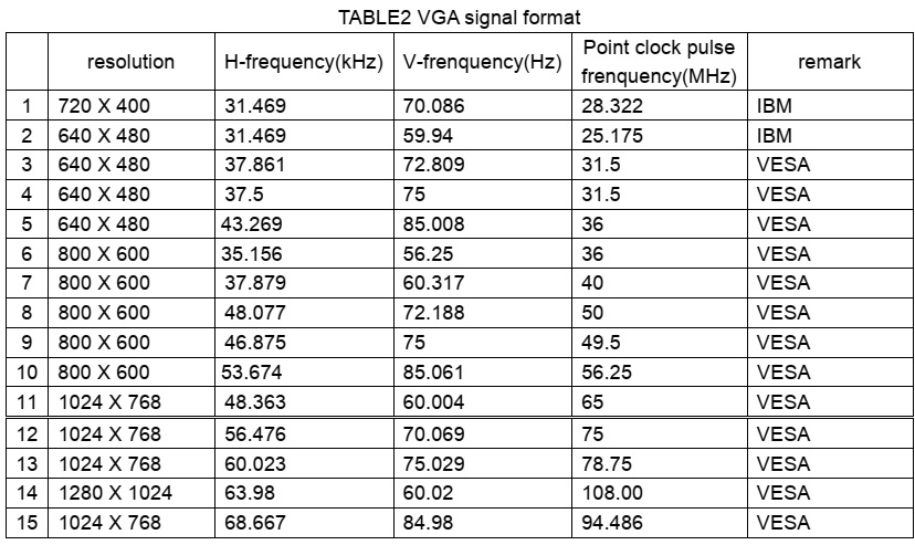
Input the VGA signal (VG-848 signal generator), separate input VGA format signal of table 1, check if the image and sound is normal. If the image is deflection of the H-field, select auto sync correction of the SCREEN menu. If the image is slight disturb, adjust the FINE TUNE correction of the SCREEN menu. Open the PIP mode, connect the earphone, and check if the image and sound is normal.
6.6 HDMI terminal
HDMI signal format receive the three high definition signal: 480P, 576P, 720P/50/60 Hz, 1080I/50/60 Hz, except for the table 2 signal. Check if the image (contain HDCP ON and OFF) and sound is normal. If the image is deflection of the H-field, select auto sync correction of the SCREEN menu.
Open the PIP mode, connect the earphone, and check if the image and sound is normal.


8.1 select TV channel

8.2 video menu, Mode: Standard, NR: Medium, APL:ON
8.3 sound menu, Volume: 20, Balance: 00, Equalizer: Custom, HP Volume: 20;
8.4 edit menu, Color System: Auto, Sound System: DK;
8.5 option menu, Default Zoom: Auto, Child Lock: Off, Menu Language: English, Country: UK,
WSS: OFF, Blue Screen: On.
Note: the 6.8.4 and 6.8.5 items should set according to clients require.

Method of software upgrading
1. Enter the software upgrading state of the TV
Method 1: press the VOL- button in the unit, turn on the main power switch, then the screen display black screen, but the indicator to blue.
Method 2: Enter factory menu, select the IIC-BUS OFF item.
2. Connection upgrading tools with upgrading port.
3. Dual- click IAPWriter logo, enter the upgrading states (if the PC and the IIC communication trouble, it can prompt.

4. Select the file menu load the software follow as:

5. Select WRITE DEVICE item of the device menu, till the right screen display “DONE”

Turn off the power , restart the unit.
Note: because of the software, it may be no-stabilization, the software can auto download and write.

NOTE: Do not shut the power off or turn the TV set on during the FLASH write. Otherwise it may lead to no way for flash to rewrite.

Working principle analysis of the unit
1. Analog signal flow
Antenna reception signal send to integrative tuner (contain HF and IF amplifier circuit), the tuner is controlled the command (SDA and SCL) of the MCU N301 (M16C), select appropriate channel to system switch, via HF amplifier and IF amplifier decode, output video signal of 2VPP and sound signal of 1VPP.
Sound signal (SCART1, 2 sound, AV sound, YPbPr, HDMI and D-SUB) via N581 HEF4052BT (sound diverter switch) to output signal, it send to N801(MPS3410 sound processing and volume control) switch of audio. Select right/left sound channel, their send to digital sound amplifier N803 (TPA3008) amplify, then send to speaker.
After output video signal of tuner, SCART1 video signal and RGB signal via matched resistance, the signal thought alone channel send to main decode IC(N101 SVP-EX52) video switch, A/D transition, digital decode, image scale and OSD superposition, then send to LVDS level drive for LCD screen.
AV, S-Video, SCART2 video and Y/C signal thought matched resistance, the signal send to the N506 video switch (SN74CBT3257CDR), via switching to selected signal (EX52_Y and EX52_C) to main decode IC (N101 SVP-EX52) video switch, A/D transition, digital decode, image scale and OSD superposition, then send to LVDS level drive for LCD screen.
D-sub and YPbPr signal thought matched resistance, the signal send to the N507 video switch (SN74CBT3257CDR), via switching to selected signal (EX52_YUV) to main decode IC (N101 SVP-EX52) video switch, A/D transition, digital decode, image scale and OSD superposition, then send to LVDS level drive for LCD screen.
2. Digital signal flow:
HDMI signal thought HDMI reception chip N405 (SiI9011HDMI with HDCP function), after receive, output digital format signal send to SVP-EX52 PIP channel thought image scale and OSD superposition, then send to LVDS level drive for LCD screen. The HDMI chip output audio digital format signal change to analog sound signal from N403 (CS4344 audio DA transfer chip), then N581 switched to N801 (MPS3410 sound processing and volume control).
3. TELETEXT function
This unit adopt main decode IC N101(SVP-EX52) of Trident company, it has TELETEXT decode function, after decoded, the teletext information in OSD display.

Sound processing IC (MSP3410)
Sound signal send to sound processing N801 MSP3410, and dual-circuit tuner has second SIF, it sends to N801 (stereo decode and auto volume control), N801 has audio channel switch, after switching in N581 (HEF4052BT), the audio input of GA/HDMI/YPbPr will be sent to N801 together with the audio signal of TV and AV to do the switching process. A way signal thought volume and high-low sound controlled, output the left and right audio send to digital audio amplifier N803 (TPA3008) amplify, then it send to speaker, other way signal output left-right audio send to earphone amplifier N805 (NJW1109), after audio control and power amplifier, it output to earphone socket. Other two ways signal output audio of TV out and AV out by SCART terminal of video board.

Xoceco 27 inch and 32 inch power board [SMPS] schematic diagram

L27W6 SMPS schematic

L32W5 SMPS schematic


Friday, 13 August 2021

Mitsubishi LT-55154, LT- 40164, LT-46164, LT-55164, LT-46265, LT-55265 – How to enter the service mode, service mode adjustments, back-up and restore, reset and initialization and more


Always respect voltages. While some may not be dangerous in themselves, they can cause unexpected reactions that are best avoided. Before reaching into a powered TV set, it is best to test the high voltage insulation. It is easy to do, and is a good service precaution.

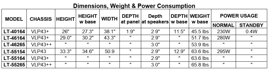
The VLP43, VLP43+ and VLP43++ chassis types. The specific models for each chassis type, dimensions and weight are listed below.


Cold Check
With the alternating current (AC) plug removed from the AC source, place a jumper across the two AC plug prongs. Connect one lead of an ohm meter to the AC plug and touch the other lead to each exposed metal part (i.e. antennas, handle bracket, metal cabinet, screw heads, metal overlay, control shafts, etc.), particularly any exposed metal part that has a return path to the chassis. The resistance of the exposed metal parts having a return path to the chassis should be a minimum of 1Meg Ohm. Any resistance below this value indicates an abnormal condition and requires corrective action.
2. Hot Check ...Use the circuit shown below to perform the hot check test.
1. Keep switch S1 open and connect the receiver to the measuring circuit. Immediately after connection, and with the switching devices of the receiver in their operating positions, measure the leakage current for both positions of switch S2.
2. Close switch S1, energizing the receiver. Immediately after closing switch S1, and with the switching devices of the receiver in their operating positions, measure the leakage current for both positions of switch S2. Repeat the current measurements of items 1 and 2 after the receiver has reached thermal stabilization. The leakage current must not exceed 0.5 milliamps (mA).


 REMOTE CONTROL USE FOR SERVICE
Many service functions and adjustments are accessed using the Remote Control.

OPTION MENU
1. Press the <MENU> button on the remote control.
2. Press the buttons <2-4-7-0>. The screen will display the Option Menu.
3. Press <EXIT> to quit.

SERVICE LEVEL INITIALIZATION
Service Level Initialization is used to restore all customer menu, video and audio settings to the original factory default condition.
1. Enter the Option Menu <MENU> <2-4-7-0>.
2. Select “Initialize” and <ENTER>

DEACTIVATE VUDU (Software Version 12.08 and higher)
This feature will deactivate the customer’s VUDU on-line subscription. It should be used before TV ownership is changed.
NOTE: This feature is independent of the Initialize function.
1. Enter the Option Menu <MENU><2-4-7-0>.
2. Select “Deactivate Vudu” and <ENTER>.
3. The “Deactivate Vudu” text will momentarily turn red.
4. Press <EXIT> to quit.
5. The TV will register as deactivated the next time it is connected to the internet.

DIGITAL SIGNAL INFORMATION
Information on the currently selected digital channel can be displayed on screen.
Note: A digital channel received using the Antenna Input must be selected first.
1. Select the Antenna Input and an active digital channel.
2. Enter the Option Menu <MENU> <2-4-7-0>.
3. Select “Digital Signal Strength” and <ENTER>.
4. Press <EXIT> to quit.


RESET / INITIALIZATION

Many customer generated symptoms, intermittent symptoms or no symptom found can be resolved by using the various Reset and Initialization options. Before visiting the customer’s home ask the customer 1st perform a System Reset by pressing the <POWER> button on the front panel and holding it for 8 seconds. If this does not resolve the issue, they can perform an A/V Reset by pressing the <INPUT> + <VOL e> buttons on the front panel at the same time and holding for 10 seconds. Then, if necessary, perform a user level Initialization by pressing <MENU><1-2-3> <ENTER> with the remote. The customer should be made aware when settings and/or options will be reset. For more information, see the chart below


BACKUP / RESTORE ISF SETTING

VLP43+ and VLP43++ models - If the customer has calibrated the ISF (ADV) video settings, the settings data can be backed up on a USB memory device. If the settings are lost due to a Reset or Initialization procedure, PWB-MAIN replacement or other reasons, the settings data can be restored.
Backup ISF Settings.
1. Insert a empty USB memory device into the USB slot.
2. Press the <MENU> button on the remote control. The Customer Menu will appear.
3. Press the <2-4-5-7> buttons. The Service Menu will appear.
4. Press the <0> button. The Data Selection Menu will appear. See below.

5 Use the <Up or Dn> buttons to select “BACKUP AND RESTORE ISF SETTING” and press <ENTER>.
6 Use the <Up or Dn> buttons to toggle to "Backup ISF Settings to USB” (Default)

7. While "Backup ISF Settings to USB” is displayed, press <ENTER>. The screen will flash the message "Backup completed."

8. Remove the USB memory device and store it in a safe place.
9. Press <MENU> to exit


Restore ISF Settings.
1. Insert the USB memory device with the backup data into the USB slot.
2. Press the <MENU> button on the remote control. The Customer Menu will appear.
3. Press the <2-4-5-7> buttons. The Service Menu will appear.
4. Press the <0> button. The Data Selection Menu will appear. See above.
5. Use the <Up or Dn> buttons to select “BACKUP AND RESTORE ISF SETTING” and press <ENTER>.
6. Use the <Up or Dn> buttons to toggle to “Restore ISF Settings From USB.”
WARNING: DO NOT press <ENTER> while "Backup ISF Settings to USB" is displayed. The data on the USB will be overwritten and lost.

7. While “Restore ISF Settings From USB” is displayed, press <ENTER>. The screen will flash the message "Restore completed." The TV will then turn off.

8. Remove the USB memory device before turning the TV back on.


To SET SCREEN SIZE

The same PWB-MAIN is used for different screen sizes within a chassis family. When a PWB-MAIN is replaced, the screen size must be set up. Failure to setup the correct screen size will result in poor picture performance.
1. Press the <MENU><2-4-5-7> buttons. The Service Menu will appear.
2. Press the <0> button. The Data Selection Menu will appear.
3. Use the <Up or Dn> buttons to select “SET SCREEN SIZE” and press <ENTER>.
4. Use the <Up or Dn> buttons to toggle to select the correct screen size and chassis of the model being serviced.
5. Press <ENTER>.
6. The Screen Size indication will flash Red momentarily to indicate the selection has been saved.


LED INDICATIONS AND SELF DIAGNOSTICS

The front panel Status LED provides an indication of the set’s operation and the possible cause of a malfunction.

A blinking red and yellow Status LED will indicate an Error Code that can help determine the cause of a circuit failure.
• The number of Red blinks indicates the value of the MSD (tens digit) of the Error Code.
• The number of Yellow blinks indicates the value of the LSD (ones digit) of the Error Code.
Example: If the Error Code is “27”, the LED will continuously blink Red two times, followed by blinking Yellow seven times.

To perform a System Reset, press and hold the side Power button for 10 seconds. Or, unplug the set for 10 seconds then restore power


Error codes and error code log

ERROR CODE LOG
The Error Code Log may be helpful to retrieve the code for an error that occurred in the past.
To access the Error Code Log: Press <MENU> <3-5-6-4>

Error Code Definitions
• PAGE - Current page number
• CURRENT TIME - total hours of operational use.
• USAGE TIME - usage hours when the error occurred.
• CODE - the specific Error Code that occurred.
• STATUS: HAPPENED - Indicates an error was recorded.
Press <CANCEL> to erase the Log.
NOTE: The Error Code Log is intended as a reference tool and is not meant to be used as a final determination of a defective part.


SOUND PROJECTOR TRANSDUCER TEST
This procedure will test will each of the TV’s speakers individually using an internal white noise generator.
1. Press the <MENU> button on the remote control. The Customer Menu will appear.
2. Press the <2-4-5-7> buttons. The Service Menu will appear.
3. Press the <0> button. The Data Selection Menu will appear. See below.

4. Use the <Up or Dn> buttons to select “SOUND PROJECTOR TRANSDUCER TEST” and press <ENTER>. The Sound Projector Transducer Test Menu will be displayed. A tone will automatically cycle from one speaker to the next as indicated on screen. Follow the instructions to manually cycle the tone.
5. Press <EXIT> or <MENU> to exit.
NOTE: The VLP43 chassis has 12 speakers. The menu will show 16 speakers with 4 greyed out.
The VLP43++ chassis includes left and right full range speakers.


Wednesday, 4 August 2021

Samsung UN43TU8000F Chassis: UWK00-How to discharge the capacitors before repair, How to disassemble and power troubleshooting


Applicable to: Samsung LED TVs: UN43TU8000F, UN50TU8000F, UN55TU8000F, UN65TU8000F, UN75TU8000F, UN85TU8000F

Before Removing SMPS board, Discharge Capacitors
• 43 inches

You have to discharge the SMPS by using service JIG across leads of Large Capacitors as pictured below.
If LED ON -> LED OFF, Discharge is completed.
Then verify voltage is less than 10Vdc across leads with Volt Meter.

• If LED ON > LED OFF discharge is completed.

Then verify voltage is less than 10Vdc across leads with Volt Meter.

Fig-50 inches
You have to discharge the SMPS by using service JIG across leads of Large Capacitors as pictured below.
If LED ON -> LED OFF, Discharge is completed.
Then verify voltage is less than 10Vdc across leads with Volt Meter.
Discharge JIG
• If LED ON > LED OFF discharge is completed. Then verify voltage is less than 10Vdc across leads with Volt Meter.


55 inches
You have to discharge the SMPS by using service JIG across leads of Large Capacitors as pictured below.
If LED ON -> LED OFF, Discharge is completed.
Then verify voltage is less than 10Vdc across leads with Volt Meter.
• If LED ON > LED OFF discharge is completed.

Then verify voltage is less than 10Vdc across leads with Volt Meter.

65 inches
You have to discharge the SMPS by using service JIG across leads of Large Capacitors as pictured below.
If LED ON -> LED OFF, Discharge is completed.
Then verify voltage is less than 10Vdc across leads with Volt Meter.
Discharge JIG
• If LED ON > LED OFF discharge is completed.

Then verify voltage is less than 10Vdc across leads with Volt Meter.

75 inches
You have to discharge the SMPS by using service JIG across leads of Large Capacitors as pictured below.
If LED ON -> LED OFF, Discharge is completed.
Then verify voltage is less than 10Vdc across leads with Volt Meter.
Discharge JIG
• If LED ON > LED OFF discharge is completed.

Then verify voltage is less than 10Vdc across leads with Volt Meter

85 inches
You have to discharge the SMPS by using service JIG across leads of Large Capacitors as pictured below.
If LED ON -> LED OFF, Discharge is completed.
Then verify voltage is less than 10Vdc across leads with Volt Meter.
Discharge JIG
• If LED ON > LED OFF discharge is completed

Then verify voltage is less than 10Vdc across leads with Volt Meter.

Disassembly

1. Push and hold down BLU connector tab to release it’s panel lock connection.

2. Lift to release the lock tab on upper left side of Board. (Step 4 will assist)

3. Locate a notch in insulation sheet. (not all models)

1. Push and hold down BLU connector tab to release it’s panel lock connection.

2. Lift to release the lock tab on upper left side of Board. (Step 4 will assist)

3. Locate a notch in insulation sheet. (not all models)

4. Use Open Jig in notch to help release & smoothly slide SMPS to the Right. (While pushing BLU Tab & Releasing Lock Tab)

Power Troubleshooting

 FUNCTION/IR Control Test

1. Place TV in Power Standby
2. Check LED Status
3. If LED is OFF
 Check LED 1.7Vdc (pin 14 ) and VCC for 5Vdc (pin 4 )
→ If missing suspect Function Assy/Cable/Main board.
4. If LED is ON
 Check Switch Operation activates on screen display.

If missing:
 Check KEY_INPUT1 (pin 11 ) change to 0V with a command.
• If wrong voltage or no change:
 Check Switch for stuck or miss-operation.
5. Check IR (pin 10 ) operation with Standard Remote command changes. (5V to 3.3V effective DC)
6. Check SDA (pin 17 ), SCL (pin 15 ) for effective 5Vdc (after power on)
→ If missing suspect Function Assy/Cable Assy/Main Assy.

FUNCTION/IR Control Test of Function/Wi-Fi /BT Module

1. Place TV in Power Standby
2. Check LED Status
3. If LED is OFF
Check LED (pin 17 ) and VCC for 5Vdc (pin 7 )
→ If missing suspect Function Assy/Cable/Main board.
4. If LED is ON
Check Switch Operation activates on screen display.

If missing:
Check KEY_INPUT1 (pin 11 ) change to 0V with a command.
• If wrong voltage or no change:
 Check Switch for stuck or miss-operation.
5. Check IR (pin 10 ) operation with Standard Remote command changes. (5V to 3.3V effective DC)
6. Check SDA (pin 14 ), SCL (pin 13 ) for effective 5Vdc (after power on)
→ If missing suspect Function Assy/Cable Assy/Main Assy.

Power supply board (SMPS) connector voltages. – 43 and 50 inches

55 and 65 inches

75 and 85 inches


Sunday, 25 July 2021

Sanyo JCX2300K stereo receiver (Australia) – alignment-circuit diagram (Schematic)-STK-078 POWER IC


Alignment procedure


Schematic diagram – Tuner


Schematic diagram – power amplifier


Printed circuit board – Power amplifier and tuner


Sunday, 18 July 2021

LG Woofer amplifier SMPS schematic EAX65142702, EAX4877702 and SMPS schematics EAX64464302, EAX65100001


Woofer SMPS circuit diagram – EAX65142702

Woofer SMPS circuit diagram – EAX4877702

SMPS circuit diagram – EAX64464302

SMPS circuit diagram – EAX65100001


LG 52LG50FD, 52LG50FD-SA-Service adjustments-service mode entry-white balance adjustment-ADC component 1 RGB adjustment and more

  These adjustments are similar to 42LB7DF Because this is not a hot chassis, it is not necessary to use an isolation transformer. However...