Saturday, 20 August 2022

EAY6451101- LG 49UJ6300 WebOS 3.5 UHD TV power supply board - How to check, layout and voltage readings


Power Supply (SMPS) Board

49UJ6300 SMPS (Power Supply)

P801- to Panel Backlight Power pin 7.
P801- Pin 1 goes to Backlight Driver
Q801- (Back of SMPS)

You CAN use Smart Test Jig with the MultiGender Board on this model for SMPS test.
You CAN’T use the Smart Test Jig and Vx1 Cable for Panel Test in this model.

P201 Power Supply Connector Voltage and Diode Check

PWR-On Pin 1: Turns on 13.2V to the Main. No backlights at this time.
Backlight Power is 107V~110V

MS (DRV- On) Pin 11: Turns on the Backlights. Backlight power goes to 158V.

Note: During STBY, LED+ will fluctuate 107V-110V.
With Main disconnected 98V

PDIM Pin 12: Will vary according to incoming video IRE level and OSD Backlight setting Output from the Video Processor. And the Backlight settings in the Customer’s Menu 0% TO 100%. It is then routed out P1001 to P201 and sent to the LED Driver IC on the Back of the SMPS.


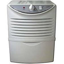
Zenith ZD30 Dehumidifier wiring diagram, repair, connection diagram and exploded view


ZD30 ZENITH DEHUMIDIFER

Equipment's needed for repair


ZD30 connection wiring diagram


Connection to the circuit board


Exploded view


Friday, 5 August 2022

The Harman Kardon CA260 Hi-Fi car amplifier schematic diagram and adjustments


60 watts per channel into 4 Ohms

90 watts per channel into 2 Ohms

180 watts bridged mono into 4 ohms

HARMAN CARDON CA260 HI FI CAR AUDIO AMPLIFIER

PROTECTION CIRCUIT

If the temperature inside the CA260 rises above 80 the protection circuit comes into operation, decreasing output. At this time the protect indicator blinks. If the temperature comes back below 80 C by natural cooling,
output returns as it was.
If the temperature rises above 100 , the power supply circuit is shut off . Not only does the output stop, but also the protect indicator goes out. If this happens, it is possible that the CA260 is broken. However, even in
this state, it cannot be always said that it is broken because the unit may operate when the temperature comes back below 80 C by natural cooling.

Protection circuit schematic

-Idling current adjustment
Conditions: Connect the DC voltmeter between TPl and TP2 and between TP3 and TP4.
-Connect a 13. 8V power supply to the 12V Battery Power In terminal.
-After the power on, wait for 5 minutes before measuring to be sure of the most stable operation.

Inspection:
-Confirm that the idling current is 50mA :t 20mA (voltage: 33mV:t 13mV).
If the current measured does not fall within the range specified , adjust it with the procedure below.

Schematic diagram


Tuesday, 2 August 2022

TCL 50P65US SMPS and Audio Output SCHEMATIC


TCL 50P65US SMPS SCHEMATIC

TCL 50P65US Backlight Schematic

TCL 50P65US-PSU connector 12Volt and connector 12Volt to 5Volt

TCL 50P65US-12VPSU TO 3.3V STB and 12V TO 1.5V CPU POWER

TCL 50P65US-5V TO 1.10V Core Power

TCL 50P65US-AD82587D – Audio Output Power schematic


Saturday, 9 July 2022

Vacuum tube (valve) amplifier circuit diagram using Valves EF86, 12AX7, 6L6, ECC83 and using power transistors 2N3055


Power amplifier using EF86, 12AX7, 26I6GC  Valves (Vintage sets)


Power amplifier using 2N3055 Power transistor

Yamaha WIRELESS SUBWOOFER NS-WSW42 how to update the software, protection details, error codes, schematic (Circuit diagram)


FRONT SURROUND SYSTEM YAS-207 or ATS-2070

CENTER UNIT YAS-CU207orATS-CU2070

When accepting a repair order from the user, it is recommended to receive the YAS-CU207/ATS-CU2070 and NS-WSW42 as a set for the repair work.

Turning on the power to YAS-CU207- ATS-CU2070 makes wireless connection of YAS-CU207- ATS-CU2070 and NS-WSW42 possible. After the repair work, if their wireless connection is not made automatically, makes
it possible manually. (For details, refer to “PAIRING THE CENTER UNIT AND SUBWOOFER MANUALLY”.)

Lithium batteries: CAUTION
Danger of explosion if battery is incorrectly replaced.
Replace only with the same or equivalent type.

YAS-CU207 - ATS-CU2070 - NS-WSW42 updating firmware

When the following part is replaced, the firmware must be updated to the latest version.
MAIN P.C.B.

Confirmation of firmware version
*
It is not possible to check the firmware version before and after updating the firmware.

Initializing the back-up IC

After updating the firmware, the back-up IC MUST be initialized by the following procedure store the setting information properly.

Connect the power cable of this unit to the AC outlet and turn off the power.
Then, while touching the  (volume –) key, touch the  (power) key, and all indicators will flash and initialization will be completed.

Required Tools
• USB storage device
(For USB2.0 High speed)
• Latest firmware

Preparation
1. Download the latest firmware from the specified
download source to the folder of the PC.
2. Copy the latest firmware from the PC to the root
folder of the USB storage device.
Note: When the latest firmware is copied to a subfolder of the USB storage device, the update will not proceed.

Operation Procedures
*
Disconnect the power cable of this unit from the AC outlet.
1. Insert the USB storage device to the UPDATE ONLY jack.
2. Connect the power cable of this unit to the AC outlet.
3. Turn off the power of this unit. (Fig. 1)
4. Keep touching the  (volume –) and  (power) keys until the CLEAR VOICE indicator flashes.
Update of the firmware starts automatically.

(If writing of the firmware has failed, disconnect the power cord from the AC outlet and perform the firmware updating procedure again from the beginning.)

5. When writing of the firmware is completed, all indicators flash.
6. Touch the  (power) key to turn off the power.
7. Remove the USB storage device from the UPDATE ONLY jack.

List of error display

Protection display

If there is anything abnormal with this unit, its protection function works to turn off the power even if it is turned on.
Touch the (power) key again to turn on the power, and the DD / DTS indicator indicates the causal factor of the protection function.

Flashing pattern
For the protection function display, the same flashing pattern is repeated 5 times.

Schematic diagram


Monday, 13 June 2022

Aiwa CT X5500, CT Z5500, CT X5200, CT Z5200, CT X5300 – Stereo Cassette Car Receiver - schematic diagram

Mechanism types

CT X5500, CT Z5500 – Basic Mechanism CDS-50-WP1

CT X5200, CT Z5200 – CT X5300 - Basic Mechanism CDS-50-WP2

Semiconductor Bases

Schematic – CTX5200, CTZ5200, CTX5300


Schematic CTX5500, CTZ5500


Logic board schematic


LG 52LG50FD, 52LG50FD-SA-Service adjustments-service mode entry-white balance adjustment-ADC component 1 RGB adjustment and more

  These adjustments are similar to 42LB7DF Because this is not a hot chassis, it is not necessary to use an isolation transformer. However...