Thursday, 18 June 2020

PANASONIC SA-MAX200PH - CD Stereo System – Service mode, factory reset, Self diagnostic mode, CD Mechanism Error Codes, SMPS Power supply schematic - C1ZBZ0004646

PANASONIC SA-MAX200PH Service Mode
Cold-Start
Here is the procedure to carry out cold-start or initialize to shipping mode.
1. Unplug AC power cord
2. Press & hold [POWER] button
3. Plug AC power cord while [POWER] button being pressed FL Display will show “_ _ _ _ _ _ _ _”
4. Release [POWER] button.

Doctor Mode

To enter into Doctor Mode

In CD Mode:
1. Press [STOP ] button on main unit follow by [4] and [7] on remote control.
2. To exit, press [DELETE] button on remote control or, press [POWER] button on Main Unit

EEPROM checksum check

Displaying of
1. Year Develop.
2. Model Type.
3. ROM Type.
4. Firmware Version.

In CD mode:
1. Enter into Doctor Mode

Volume Setting Check
To check the volume setting of the main unit.

In Doctor mode:
1. Press [1] button on the remote control.
2. To cancel this mode, press [0] button on the remote control.

FL Display Check
To check the FL segment display.
All segments will light up while all LED blink at 0.5s intervals.

In Doctor mode:
1. Press [1] button on the remote control.
2. To cancel this mode, press [0] button on the remote control.

Traverse Test

To determine the traverse unit operation for inner & outer access track.
In this mode,ensure the CD is in the main unit.

In Doctor Mode:
2. To cancel this mode, press [0] button on the remote control.
1. Press [10] [1] [2] button on the remote control.

Reliability Test (Combination)
To determine the traverse unit
operation & open/close operation of the mechanism.
In this mode,ensure the CD is in the main unit.

In Doctor Mode:
1. Press [10] [1] [5] button on the remote control.

Loading Test

To determine the open & close operation of the CD Mechanism Unit.

In this mode, the tray will open & close automatically.

In Doctor Mode:
1. Press [10] [2] [1] button on the remote control.
2. To cancel this mode, press [0] button on the remote control.

CD Self- Adjustment Test
To display result of self-adjustment for CD.

In Doctor Mode:
1. Press [10] [1] [4] button on the remote control.
To cancel this mode, press [0] button on the remote control.

CD LSI Version Check
For checking CD LSI Version and checksum information.

In Doctor Mode:
1. Press [4] button on the remote control.
To cancel this mode, press [0] button on the remote control.

Self Diagnostic Mode

To enter into self diagnostic checking

Step 1: Select CD mode (Ensure no disc is inserted).
Step 2: Press & hold [ STOP ] button follow by [ SEEK /FORWARD] on main unit for 2 seconds.

Error code information

System will perform a check on any unusual/error code from the memory
Step 1: In self diagnostic mode, Press [STOP] on main unit.
To exit, press [^/I] on main unit or remote control.

Delete error code

To clear the stored in memory (EEPROM IC)
Step 1: In self diagnostic mode, Press [0] on remote control.
To exit, press [^/I] on main unit or remote control.

Cold Start

To active cold start upon next AC power up when reset start is execute the next time.

In self diagnostic mode:
1. Press [3] button on the remote control.

Self-Diagnostic Error Code Table
Self-Diagnostic Function provides information on any problems occurring for the unit and its respective components by displaying the error codes. These error code such as U**, H** and F** are stored in memory and held unless it is cleared. The error code is automatically display after entering into self-diagnostic mode.
CD Mechanism Error Codes (CD Mechanism Unit)

CD H15

CD Open Abnormal

During operation POS_SW_R On fail to be detected with 4 sec. Erro No. shall be clear by force during cold start.

Press [STOP ] on main unit for next error.

CD H16 CD

Closing Abnormal

During operation POS_SW_CEN On fail to be detected with 4 sec. Error No. shall be clear by force or during cold start.

Press [ STOP ] on main unit for next error.

F26

Communication between CD servo LSI and micro-p abnormal.
During switch to CD function, if SENSE = “L” within failsafe time of 20ms.

Press [STOP] on main unit for next error.

Sales Demonstration Lock Function
Entering into Sales demonstration lock mode
Here is the procedures to enter into the Sales demonstration lock mode.
Step 1: Turn on the unit.
Step 2: Select to any mode function.
Step 3: Press and hold [ OPEN/CLOSE] and [CD] keys for 5 sec or more.
The display will show upon entering into this mode for 2 sec.

Note: [ OPEN/CLOSE] button is invalid and the main unit displays “LOCKED” while the lock function mode is entered.

Cancellation of Sales demonstration lock mode
Step 1: Turn on the unit.
Step 2: Select to any mode function.
Step 3: Set volume to Vol 19.
Step 4: Press and hold [ OPEN/CLOSE] and [CD] keys for 5 sec or more.
The display will show upon entering into this mode for 2 sec.


How to enter to servie mode -AOC 2216 LCD MONITOR, SMPS circuit

AOC 2216 SERVICE MODE

How to enter to service mode

Turn on power, press the Menu button, pull out the power cord, and then plug the power cord. Then the factory OSD will be at the left top of the panel.

 Adjust the Picture 

1.Press the MENU-button to activate the OSD window.

2.Press+ or - to navigate through the functions. Once the desired function is highlighted, press the ENU-button to activate it. If the function selected has a sub-menu, press or again to navigate through the sub-menu unctions.Once the desired function is highlighted, presses MENU-button to activate it.

3.Press+ or - to change the settings of the selected function. To exit and save, select the exit function. If you want to adjust any other function, repeat steps 2-3.

OSD Lock Function: To lock the OSD, press and hold the MENU button while the monitor is off and then press power button to turn the monitor on. To un-lock the OSD - press and hold the MENU button while the monitor is off and then press power button to turn the monitor on.

4.Press Exit key continually for 7 sec. to turn on or off DDC-CI.

White- Balance, Luminance Adjustment 

Approximately 30 minutes should be allowed for warm up before proceeding White-Balance adjustment.

1. How to do the Chroma-7120 MEM .Channel setting

A. Reference to chroma 7120 user guide

B. Use “SC” key and “NEXT” key to modify xyY value and use “ID” key to  modify 

the TEXT description Following is the procedure to do white-balance adjust

2. Setting the color temp. You want

A. 9300 color:

9300k color temp. parameter is x = 283 ±25, y = 297 ±25, Y = 180 ±25 cd/m2 ,    

B. 7300 color:

7300k color temp. parameter is x = 299 ±25, y = 315 ±25, Y = 180 ±25 cd/m2 

C. 6500 color:

6500k color temp. parameter is x = 313 ±25, y = 329 ±25, Y = 180 ±25 cd/m2   

D.SRGB

SRGB color temp. parameter is x = 313 ±25, y = 329 ±25, Y = 150 cd/m2

 3. Enter into factory mode of 2216Sw

 Turn on power, press the Menu button, pull out the power cord, and then plug the power cord. Then the factory OSD will be at the left top of the panel.

 4. Bias adjustment:

Set the Contrast to 90

Adjust the Brightness  to 100.

 5. Gain adjustment :

Move cursor to “-F-” and press MENU key

A. Adjust 9300k color-temperature           

1. Switch the Chroma-7120 to 9300k channel.

2. The chroma 7120 will show x = 283 ±25, y = 297 ±25, Y = 180 ±25 cd/m2

3. Switch the chroma-7120 to RGB MODE (with press “MODE” button to change)

4. Adjust the RED of color 9300K on factory window until chroma 7120 indicator reached the value   R=100

5. Adjust the GREEN of color 9300K on factory window until chroma 7120 indicator reached the value  G=100                    

6. Adjust the BLUE of color 9300K on factory window until chroma 7120 indicator reached the value  B=100 

7. Repeat above procedure (item 4, 5, 6) until chroma 7120 RGB value meet the tolerance =100±2

B. Adjust 7300k color-temperature

1. Switch the chroma-7120 to 7300k channel.

2. The chroma 7120 will show x = 299 ±25, y = 315 ±25, Y = 180 ±25 cd/m2

3. Switch the chroma 7120 to RGB MODE (with press “MODE” button to change)

4. Adjust the RED of color 7300k on factory window until chroma 7120 indicator reached the value R=100

5. Adjust the GREEN of color 7300k on factory window until chroma 7120 indicator reached the value G=100

6. Adjust the BLUE of color 7300k on factory window until chroma 7120 indicator reached the value B=100

7. Repeat above procedure (item 4, 5, 6) until chroma 7120 RGB value meet the tolerance =100±2

C. Adjust 6500k color-temperature

1. Switch the chroma-7120 to 6500K channel.

2. The chroma 7120 will show x = 313 ±25, y = 329 ±25, Y = 180 ±25 cd/m2

3. Switch the chroma 7120 to RGB MODE (with press “MODE” button to change)

4. Adjust the RED of color 6500K on factory window until chroma 7120 indicator reached the value R=100

5. Adjust the GREEN of color 6500K on factory window until chroma 7120 indicator reached the value G=100

6. Adjust the BLUE of color 6500K on factory window until chroma 7120 indicator reached the value B=100

7. Repeat above procedure (item 4, 5, 6) until chroma 7120 RGB value meet the tolerance =100±2

 D. Adjust SRGB color-temperature

1. Switch the chroma-7120 to SRGB channel.

2. The chroma 7120 will show x = 313 ±25, y = 329 ±25, Y = 150cd/m2

3. Switch the chroma 7120 l to RGB MODE (with press “MODE” button to change)

4. Adjust the RED of color sRGB on factory window until chroma 7120 indicator reached the value R=100

5. Adjust the GREEN of color sRGB on factory window until chroma 7120 indicator reached the value G=100

6. Adjust the BLUE of color sRGB on factory window until chroma 7120 indicator reached the value B=100

7. Repeat above procedure (item 4, 5, 6) until chroma 7120 RGB value meet the tolerance =100±2

E. Press reset key and Turn the Power-button “off to on” to quit from factory mode.

SMPS [Power board] schematic

Thursday, 11 June 2020

How to disassemble Philips MCM275 Microsystem, full schematic

MCM275 Philips Microsystem, disassemble procedure, circuit diagram [full schematic]

1) Press the 2 latches and push the Panel as shown in fig.

2) Loosen the 5 screws A and 6 B to remove the Rear Cabinet as shown in fig. 2.

3) Loosen the 3 screws C to remove the SP & ANT panel as shown in fig. 3.

4) Loosen the 5 screws D to remove the Power Module as shown in fig. 3

5) Loosen the 2 screws E and remove the Support Panel as shown in fig. 4.

6) Loosen the 3 screws F to remove the Main Panel as shown in fig. 5.

Disassembly of the Lens Display and the Volume button

1) Use a screwdriver to pull in the direction shown in fig. 6.

2) Place two small screwdrivers between the front of the case and the button and lift it up, removing the Volume button as shown in fig. 7.

Disassembly of the CD Module and CD Holder

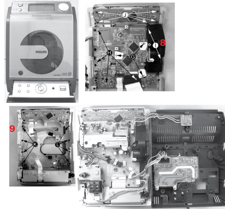
1) Loosen the 5 screws J of the Keyboard Panel in the Front Cabinet to remove it as shown in fig. 8.

2) Loosen the 4 screws H and 3 G of the CD Module as shown in fig. 8.

3) Loosen the 2 screws I to remove the Motor Mechanism from the Servo as shown in fig. 8.

4) Loosen the 4 K screws to remove the Right CD Door and the 4 L screws to remove the Left CD Door as shown in fig. 9.

Note: After reassembly, it is very important to ensure that all wires are properly fitted so that they do not touch / obstruct the movement of the parts.

Schematic


Friday, 5 June 2020

Wednesday, 27 May 2020

DENON DBP – 1610 Service mode – Initialization - Network firmware update – factory reset – Try lock – remote lock

DENON DBP-1610: how to initialize the blu-ray disc player
To put the program back at the factory-default, initialize the BD player as the following procedure.
1. Turn the power on.
2. Remove the disc on the tray and close the tray.
3. Press [1], [2], [3], [4], and [DISPLAY] buttons on the remote control unit in that order.4. Press [ STOP ] button on the remote control unit. CLEAR appears on the VFD.
5. To exit this mode, press [POWER OFF] button.
firmware renewal mode
Note: The file extension of the available firmware is “b20”.
1. Turn the power on and remove the disc on the tray and close the tray.
2. To put the BD player into version up mode, press [9], [8], [7], [6], and [POP UP MENU/MENU] buttons on the remote control unit in that order.
The tray will open automatically.
3. Load the disc for version up.
4. The BD player enters the F/W version up mode automatically. Make sure to insert the proper F/W for the state of this model.
5. After programming is finished, the checksum on the VFD.
Checksum appears on the VFD then the tray will open automatically. Remove the disc on the tray. At this time, no button is available.
6. Unplug the AC cord from the AC outlet. Then plug it again.
7. Turn the power on.
8. Press [1], [2], [3], [4], and [DISPLAY] buttons on the remote control unit in that order.
9. Press [ STOP ] button on the remote control unit.
To exit this mode, press [POWER OFF] button.
Network Firmware Update
1. Press [SETUP] button on the remote control unit in stop mode.
2. Use [LEFT/ RIGHT] button to select “CUSTOM”, then press [ENTER] button.
3. Use [LEFT/ RIGHT] button to select “Other”, then press [ENTER] button.
4. Use [UP / DOWN] button to select “Network Update”, then press [ENTER] button. Confirmation message will appear.
5. Use [UP/ DOWN] button to select “Yes”, then press [ENTER] button.
This unit will start checking for the latest firmware version.
NOTE:
If any error message concerning the network environment appears, please confirm the setting of your unit according to the error message. If you need to change any of your network environmental setting in order to execute the update, please contact to the internet service provider.
6. Confirmation message will appear.
Use [UP/ DOWN] button to select “Yes”, then press [ENTER] button.
The unit will start downloading the latest firmware version.
7. When the download completes, confirmation message will appear.
Press [ENTER] button.
The unit will start updating the firmware version. It may take a while to complete the updating.
(Please wait until “100%” appears on the front panel display.)
8. After updating finishes, this unit will restart and open the disc tray automatically.
How to Verify the Firmware Version
1. Turn the power on.
2. Remove the disc on the tray and close the tray.
3. Press [1], [2], [3], [4], and [DISPLAY] buttons on the remote control unit in that order.
4. To exit this mode, press [POWER OFF] button.
Entering Service Mode
In power on condition, no discs and tray close, it will be entered into service mode by the following operation using the remote controller. However, it will not be entered when Media Select Item is SD Memory.
Service Mode by using remote controller
Press the following buttons on the remote controller in power on condition, no discs and tray close; [2]>[5]>[8]>[0]>[CLEAR]
Release from Service Mode
Press the [POWER OFF] button to turn off power.
Screen saver/Auto Power Off in Service Mode
These functions are not performed in Service Mode.
tray lock mode
Tray Lock Mode prevents the tray opening or closing to prevent disc theft in demo mode.
Enter this mode using the following procedure.
1. Confirm that the TV Monitor is connected.
2. With playback stopped, press [SETUP], [TOP MENU], [3], [AUDIO], [0] and [SETUP] buttons on the remote control unit in that order. "Trade-On" appears in the upper right corner on the screen.
3. To exit this mode, press [SETUP], [TOP MENU], [3], [AUDIO], [0] and [SETUP] buttons on the remote control unit in that order. "Trade-Off" appears in the upper right corner on the screen,
remote lock mode
SETTING MENU
Remote Lock Off Mode:
This mode receives an input signal from the remote control unit or from the Remote In-Jack on the rear panel.
Remote Lock On Mode:
This mode dose not receive an input signal from the remote control unit or from the Remote In-Jack on the rear panel.
Perform the setting using the following procedure.
1. Press [POWER ON] and [STOP] buttons on the front panel simultaneously for over 3 seconds to set "Remote Lock Mode" and display mode.
2. Press [STILL/PAUSE] button on the front panel to set to "On" or "Off". When "Remote Lock On", "Remote Lock On" will appear in the upper right corner on the screen.
When "Remote Lock Off", "Remote Lock Off" will appear in the upper right corner on the screen.
a.       If [STILL/PAUSE] button is not pressed for 2 seconds or any other button is pressed within 2 seconds, the unit will be released from "Remote Lock Mode".
b. When initializing, set the Remote Lock Mode "off".

LG 52LG50FD, 52LG50FD-SA-Service adjustments-service mode entry-white balance adjustment-ADC component 1 RGB adjustment and more

  These adjustments are similar to 42LB7DF Because this is not a hot chassis, it is not necessary to use an isolation transformer. However...