Thursday, 11 June 2020

How to disassemble Philips MCM275 Microsystem, full schematic

MCM275 Philips Microsystem, disassemble procedure, circuit diagram [full schematic]

1) Press the 2 latches and push the Panel as shown in fig.

2) Loosen the 5 screws A and 6 B to remove the Rear Cabinet as shown in fig. 2.

3) Loosen the 3 screws C to remove the SP & ANT panel as shown in fig. 3.

4) Loosen the 5 screws D to remove the Power Module as shown in fig. 3

5) Loosen the 2 screws E and remove the Support Panel as shown in fig. 4.

6) Loosen the 3 screws F to remove the Main Panel as shown in fig. 5.

Disassembly of the Lens Display and the Volume button

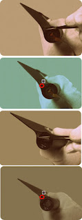
1) Use a screwdriver to pull in the direction shown in fig. 6.

2) Place two small screwdrivers between the front of the case and the button and lift it up, removing the Volume button as shown in fig. 7.

Disassembly of the CD Module and CD Holder

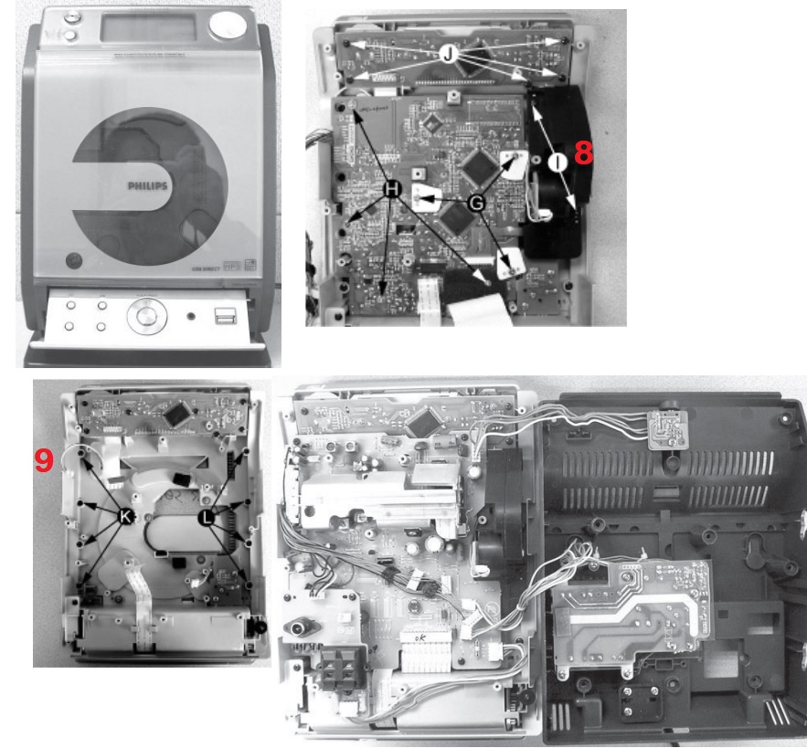
1) Loosen the 5 screws J of the Keyboard Panel in the Front Cabinet to remove it as shown in fig. 8.

2) Loosen the 4 screws H and 3 G of the CD Module as shown in fig. 8.

3) Loosen the 2 screws I to remove the Motor Mechanism from the Servo as shown in fig. 8.

4) Loosen the 4 K screws to remove the Right CD Door and the 4 L screws to remove the Left CD Door as shown in fig. 9.

Note: After reassembly, it is very important to ensure that all wires are properly fitted so that they do not touch / obstruct the movement of the parts.

Schematic


Friday, 5 June 2020

Wednesday, 27 May 2020

DENON DBP – 1610 Service mode – Initialization - Network firmware update – factory reset – Try lock – remote lock

DENON DBP-1610: how to initialize the blu-ray disc player
To put the program back at the factory-default, initialize the BD player as the following procedure.
1. Turn the power on.
2. Remove the disc on the tray and close the tray.
3. Press [1], [2], [3], [4], and [DISPLAY] buttons on the remote control unit in that order.4. Press [ STOP ] button on the remote control unit. CLEAR appears on the VFD.
5. To exit this mode, press [POWER OFF] button.
firmware renewal mode
Note: The file extension of the available firmware is “b20”.
1. Turn the power on and remove the disc on the tray and close the tray.
2. To put the BD player into version up mode, press [9], [8], [7], [6], and [POP UP MENU/MENU] buttons on the remote control unit in that order.
The tray will open automatically.
3. Load the disc for version up.
4. The BD player enters the F/W version up mode automatically. Make sure to insert the proper F/W for the state of this model.
5. After programming is finished, the checksum on the VFD.
Checksum appears on the VFD then the tray will open automatically. Remove the disc on the tray. At this time, no button is available.
6. Unplug the AC cord from the AC outlet. Then plug it again.
7. Turn the power on.
8. Press [1], [2], [3], [4], and [DISPLAY] buttons on the remote control unit in that order.
9. Press [ STOP ] button on the remote control unit.
To exit this mode, press [POWER OFF] button.
Network Firmware Update
1. Press [SETUP] button on the remote control unit in stop mode.
2. Use [LEFT/ RIGHT] button to select “CUSTOM”, then press [ENTER] button.
3. Use [LEFT/ RIGHT] button to select “Other”, then press [ENTER] button.
4. Use [UP / DOWN] button to select “Network Update”, then press [ENTER] button. Confirmation message will appear.
5. Use [UP/ DOWN] button to select “Yes”, then press [ENTER] button.
This unit will start checking for the latest firmware version.
NOTE:
If any error message concerning the network environment appears, please confirm the setting of your unit according to the error message. If you need to change any of your network environmental setting in order to execute the update, please contact to the internet service provider.
6. Confirmation message will appear.
Use [UP/ DOWN] button to select “Yes”, then press [ENTER] button.
The unit will start downloading the latest firmware version.
7. When the download completes, confirmation message will appear.
Press [ENTER] button.
The unit will start updating the firmware version. It may take a while to complete the updating.
(Please wait until “100%” appears on the front panel display.)
8. After updating finishes, this unit will restart and open the disc tray automatically.
How to Verify the Firmware Version
1. Turn the power on.
2. Remove the disc on the tray and close the tray.
3. Press [1], [2], [3], [4], and [DISPLAY] buttons on the remote control unit in that order.
4. To exit this mode, press [POWER OFF] button.
Entering Service Mode
In power on condition, no discs and tray close, it will be entered into service mode by the following operation using the remote controller. However, it will not be entered when Media Select Item is SD Memory.
Service Mode by using remote controller
Press the following buttons on the remote controller in power on condition, no discs and tray close; [2]>[5]>[8]>[0]>[CLEAR]
Release from Service Mode
Press the [POWER OFF] button to turn off power.
Screen saver/Auto Power Off in Service Mode
These functions are not performed in Service Mode.
tray lock mode
Tray Lock Mode prevents the tray opening or closing to prevent disc theft in demo mode.
Enter this mode using the following procedure.
1. Confirm that the TV Monitor is connected.
2. With playback stopped, press [SETUP], [TOP MENU], [3], [AUDIO], [0] and [SETUP] buttons on the remote control unit in that order. "Trade-On" appears in the upper right corner on the screen.
3. To exit this mode, press [SETUP], [TOP MENU], [3], [AUDIO], [0] and [SETUP] buttons on the remote control unit in that order. "Trade-Off" appears in the upper right corner on the screen,
remote lock mode
SETTING MENU
Remote Lock Off Mode:
This mode receives an input signal from the remote control unit or from the Remote In-Jack on the rear panel.
Remote Lock On Mode:
This mode dose not receive an input signal from the remote control unit or from the Remote In-Jack on the rear panel.
Perform the setting using the following procedure.
1. Press [POWER ON] and [STOP] buttons on the front panel simultaneously for over 3 seconds to set "Remote Lock Mode" and display mode.
2. Press [STILL/PAUSE] button on the front panel to set to "On" or "Off". When "Remote Lock On", "Remote Lock On" will appear in the upper right corner on the screen.
When "Remote Lock Off", "Remote Lock Off" will appear in the upper right corner on the screen.
a.       If [STILL/PAUSE] button is not pressed for 2 seconds or any other button is pressed within 2 seconds, the unit will be released from "Remote Lock Mode".
b. When initializing, set the Remote Lock Mode "off".

Saturday, 16 May 2020

How to disassemble Lenovo tablet - Lenovo YOGA Tablet 2-1371F - How to test the charger – How to remove the battery – How to remove the cover

Lenovo YOGA Tablet 2-1371F How to disassemble the tablet

To verify a symptom, follow the steps below:
1. Turn off the computer.
2. Remove the battery pack.
3. Connect the AC adapter.
4. Make sure that power is supplied when you turn on the computer.
5. Turn off the computer.
6. Disconnect the AC adapter and install the charged battery pack.
7. Make sure that the battery pack supplies power when you turn on the computer.
If you suspect a power problem, see the appropriate one of the following power supply checkouts:
“Checking the Computer AC Charger” 
“Checking the internal battery status” 
Checking the Computer AC Charger
When you use the computer AC Charger to charge the tablet but no power is charged, see the instructions in this topic to check the computer AC Charger.
To check the computer AC Charger, do the following:
1. Disconnect the micro-USB cable from the tablet.
2. Measure the output voltage across the connector marked B of the micro-USB cable. Refer to the following figure:

Note: The output voltage across pin 3 of the micro-B connector might be different from the one you are servicing.

3. If the voltage is not correct, replace the micro-USB cable.
4. If the voltage is acceptable, replace the system board.

Checking the internal battery status
To check the battery status of the tablet, do either of the following:
Approximate information about the battery status
Get the approximate status of the battery at any time by checking the battery status icon on the system bar in the upper-right corner of the screen. The shorter the green bar is, the less the battery power remains.
Accurate information about the battery status
To get the accurate information about the battery status of the tablet, do the following:
1. Open the Android Settings screen.
To open the Android Settings screen, do either of the following:

 From the main Home screen, touch the Android Settings icon on
Lenovo Launch Zone. The Android Settings screen is displayed.
Pull down the application icon from the action bar and then touch Settings. The Android Settings screen is displayed.
2. Touch Battery in the Device section on the Android Settings screen.
3. The accurate percentage of the remaining battery power is shown on the screen.

DISASSEMBLING PROCEDURE 

How to remove Rear cover
1. Push the button to unlock the hinge frame.

2. Open the hinge frame.

3. Open the card slot cover using a thin flat blade or guitar pick.

4. Remove screws 1 on the rear cover as shown in the figure below.

5. Separate the bottom right corner of the rear cover from the main body of the tablet using a suction tool as shown in the figure below.

6. Hold the tablet in one hand and use a guitar pick to unlock the rear cover from the tablet along the joint line as shown in the figure below.

7. Slowly remove the rear cover.

How to remove Battery pack

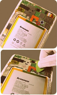
1. Remove screws 1 on the metal piece for fixing the battery FPC as shown in the figure below.

2. Remove the metal piece using a pair of pointed tweezers.

3. Disconnect the power supply to the tablet by detaching the battery FPC from its connectors on the main board using a pair of tweezers.

4. Remove the HDMI and audio jack FPC FRU.
5. Remove the right speaker FRU.
6. Remove the HDMI and audio jack FPC holder, by lifting the holder, and at the same time pushing the holder in the direction using a pair of tweezers as shown in the figure below.

7. Place the hinge frame in the closed position as shown in the figure below.

8. Slowly pull out the hinge pivot on the left side of the battery pack using a pair of tweezers.

9. Detach the connector of the USB and power key FPC from the main board using a pair of tweezers.

10. Remove the USB FPC holder, by lifting the USB FPC holder using a pair of tweezers, and at the same time pushing the USB FPC holder in the direction shown in the figure below.

11. Slowly pull out the hinge pivot on the right side of the battery pack using a pair of tweezers.

12. Remove the hinge frame from the main body of the tablet as shown in the figure below.

13. Peel off the foil on the battery cover at the side of the hinge frame with battery FPC.

14. Remove screw 1 on the battery cover as shown in the figure below.

15. Peel off the foil on the battery cover at the side of the hinge frame without battery FPC.

16. Remove screw 1 on the battery cover as shown in the figure below.

17. Remove the battery cover at the side of the hinge frame without battery FPC as shown in the figure below.

18. Push out the battery pack from the hinge frame from the side of the hinge frame without battery FPC.

19. Remove the battery pack from the hinge frame.


Wednesday, 13 May 2020

Lenovo A3500 – Tablet – Disassembling procedure – How to test the AC adapter – How to remove the battery

Lenovo A3500  How to disassemble, How to remove the battery, How to check the charger
1. Turn off the computer.
2. Remove the battery pack.
3. Connect the AC adapter.
4. Make sure that power is supplied when you turn on the computer.
5. Turn off the computer.
6. Disconnect the AC adapter and install the charged battery pack.
7. Make sure that the battery pack supplies power when you turn on the computer.
If you suspect a power problem, see the appropriate one of the following power supply checkouts:
“Checking the Computer AC Charger” - “Checking the internal battery status” 
Checking the Computer AC Charger
When you use the computer AC Charger to charge the tablet but no power is charged, see the instructions in this topic to check the computer AC Charger. To check the computer AC Charger, do the following:
1. Disconnect the micro-USB cable from the tablet.
2. Measure the output voltage across the connector marked B of the micro-USB cable. Refer to the following figure:

Note: The output voltage across pin 3 of the micro-B connector might be different from the one you are servicing.
3. If the voltage is not correct, replace the micro-USB cable.
4. If the voltage is acceptable, replace the system board.

Checking the internal battery status
To check the battery status of the tablet, do either of the following:
Approximate information about the battery status
Get the approximate status of the battery at any time by checking the battery status icon on the system bar in the upper-right corner of the screen. The shorter the green bar is, the less the battery power remains.
Accurate information about the battery status
To get the accurate information about the battery status of the tablet, do the following:
1. Open the Android Settings screen.
To open the Android Settings screen, do either of the following:
From the main Home screen, touch the Android Settings icon on
Lenovo Launch Zone. The Android Settings screen is displayed.
Pull down the application icon from the action bar and then touch Settings. The Android Settings screen is displayed.
2. Touch Battery in the Device section on the Android Settings screen.
3. The accurate percentage of the remaining battery power is shown on the screen.

DISASSEMBLING PROCEDURE 

How to remove Rear cover and side key
1. Open the card slot cover on the rear cover using a guitar pick.

2. Remove screw 1 in the card slot recess.

3. Hold the tablet in one hand and use a guitar pick to unlock the rear cover from the tablet along the joint line as shown in the figure below.

4. Remove the rear cover.

How to remove Battery pack

1. Remove screw 1 for fixing the steel frame on the battery connector

2. Remove the steel frame from the front module as shown in the figure below.

3. Detach the battery FPC from its connector on the PCBA using a guitar pick.

4. Detach the battery pack from its seat by inserting a guitar pick into the joint surface and then cutting along the joint line in the direction shown in the figure below.

5. Remove the battery pack from the front module of the tablet.


Wednesday, 29 April 2020

Home security system construction using Laser beam


A low-cost, invisible laser circuit to protect your house from thieves or trespassers. A laser pointer torch, which is easily available in the market, can be used to operate this device
The block diagram of the unit shown depicts the overall arrangement for providing security to a house. A laser
torch powered by 3V power-supply is used
  for generating a laser beam.
A combination of plain mirrors M1 through M6 is used to direct the laser beam around the house to form a net. The laser beam is directed to finally fall on an LDR that forms part of the receiver unit as shown in Fig.
Any interruption of the
  beam by a thief/trespasser will result into energize the alarm. The 3V power-supply circuit is a conventional full wave rectifier-filter circuit. Any alarm unit that operates on 230V AC can be components. When switches S1 and S2 are activated, transformer X1, followed by a full-wave rectifier and smoothing capacitor C1, drives relay RL1 through the laser switch.
The laser beam should be aimed continuously on LDR. As long as the laser beam falls on LDR, transistor T1 remains forward biased and relay RL1 is thus in energized condition. When a person crosses the line of laser beam, relay RL1 turns off and transformer X2 gets energized to provide a parallel path across N/C contact and the pole of relay RL1.
In this condition, the laser beam will have no effect on LDR and the alarm will continue to operate as long as switch S2 is on.
When the torch is switched on, the pointed laser beam is reflected from a definite point/place on the periphery of the house. Making use of a set of properly oriented mirrors one can form an invisible net of laser rays as shown in the block diagram. The final ray should fall on LDR of the circuit.
Note. LDR should be kept in a long pipe to protect it from other sources of light, and its total distance from the source may be kept limited to 500 meters.
The total cost of the circuit, including the laser torch, is Rs 500/= or less.

LG 52LG50FD, 52LG50FD-SA-Service adjustments-service mode entry-white balance adjustment-ADC component 1 RGB adjustment and more

  These adjustments are similar to 42LB7DF Because this is not a hot chassis, it is not necessary to use an isolation transformer. However...