Wednesday, 12 June 2019

HOME AUDIO SYSTEM Sony MHC-V44D disassembly procedure, SMPS troubleshooting table


Speaker system
3-way, Sound Pressure Horn
Speaker unit
Tweeter L/R: 40 mm, cone type
Midrange L/R: 80 mm, cone type
Woofer: 200 mm, cone type
Rated impedance
Tweeter L/R: 4 ohms
Midrange L/R: 4 ohms
Woofer: 2 ohms

  The laser diode in the optical pick-up block may suffer electrostatic break-down because of the potential difference generated by the charged electrostatic load, etc. on clothing and the human body.
  During repair, pay attention to electrostatic break-down and also use the procedure in the printed matter which is included in the repair parts.
The flexible board is easily damaged and should be handled with care.
The laser beam on this model is concentrated so as to be focused on the disc reflective surface by the objective lens in the optical pickup block. Therefore, when checking the laser diode emission, observe from more than 30 cm away from the objective lens.
If “protectx” (x is a number) appears in the display panel
Immediately unplug the AC power cord (mains lead), and check the following items.
• Is anything blocking the ventilation holes of the unit?
• Is the USB port short-circuited?
After checking the above items and fixing any problems, plug in the AC power cord (mains lead) again and turn on the system.
Releasing the disc tray lock
The disc tray lock function for the anti-theft of an demonstration disc in the store is equipped.
Releasing Procedure:
1. Press Power button to turn the power on.
2. Press the [FUNCTION] button until the message “DVD/CD” is displayed.
3. Press the [ENTER] button and [VOCAL FADER] button simultaneously and hold down for around 3 seconds.
4. The message “UNLOCKED” is displayed and the disc tray is unlocked.
Note: When “LOCKED” is displayed, the slot lock is not released by turning power on/off with the Power button.
Note of replacing the ic2002 and ic2003 on the damp board and the complete damp board
When IC2002 and IC2003 on the DAMP board and the complete DAMP board are replaced, it is necessary to spread the compound between parts and heat sink.
How to open the tray when power switch turn off
Note 1: After the side panel and top panel are removed, this work is done.
Note 2: Prepare the thin wire (clip etc. processed to the length of 8 cm or more).
Disassembly 


Back panel section


Front panel disassembly
Speaker disassembly
Optical device disassembly

SMPS board diagnosis


Monday, 10 June 2019

ROTEL RA 980BX STEREO AMPLIFIER REPAIR ASSISTANCE


Fault: No output from left channel. The right Channel is working fine.
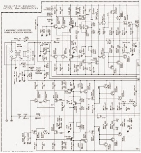
Added some photos and circuit for reference  
While testing the amp noticed that the left channel is giving switch on off thump while powering ON and OFF the amplifier. It happens when there is DC voltage flow through the speakers. It shouldn't be there. And the thump is there only on the left channel. While testing the amplifier section found that all the transistors where idling at mentioned voltage. All Base pins where around +/- 0.5volt. and the output is almost 0.012mvdc.
As the amplifier had an external Pre -IN, Pre -out coupling it was easy to use an external pre amp to test the amplifier section.
 While testing with an external pre amp found that the amplifier section is OK. There were no switch off thump too while working through the external pre amp.
After testing the amplifier stage and confirming it is OK, turn to the next stage. The internal pre amp (tone control) section.
The internal pre amp of Rotel RA 9808X is built with two AD712JN ICs. Where each AD712 is used for the left and right channel separately. Hope Rotel did it to reduce the bleeding between the left and right channel. Its possible to reduce the bleeding between two channels. If we use two op amps separately for each channels than using the half of each.
While testing the pre amplifier it is found that there was a DC voltage of 15V at the pin no 7 (output pin) of one of the AD712 which is used for the left channel. It shouldn’t be there. The output, non inverting and inverting pins of an op amp which is used in the tone stage circuit should be at 0vdc ,if it’s working in dual supply rail (+/- supply).  And there was no voltage found on the pin 7 of other AD712 which is used for the right channel.  While further treating found that the supply voltages to AD712 where ok its there it +/- 17.5V.  
As there was nothing else to check, replace the AD712 with a new one. Then power the amplifier and found that it’s working perfectly. There were no voltages where found on the pin no 7. And also there were no switch of thump too. Also replaced the power filter capacitor and coupling capacitors near the AD712 of each channel as it is found bad.
If AD712 is not available then Instead of AD712 you can use TLO82. It is an equivalent to AD712. Or you can use NE4558 , it will work too but  there will be some difference in frequency response of the amplifier, but not that much noticeable. If your customer is not an audiophile then it’s ok.  
Circuit diagram of ROTEL RA 980BX
TONE 1/2
TONE 2/2
POWER AMP 1/2
POWER AMP 2/2
Power amplifier bias adjust
Prior to adjustment run the amplifier for about 5 minutes with load resistance of 8ohms
SETP
PLUS LEAD
MINUS LEAD
ADJUST
ADJUST FOR
1
TP3
TP1
VR601
DC MILLIVLOT
10mv
2
TP4
TP2
VR602

Friday, 17 May 2019

How to disassemble Apple Mac Mini – how to remove the case – How to remove the logic board

How to remove and replace the optical diver -  How to disassemble Apple Mac Mini – how to remove the case – How to remove the logic board - Apple Mac Mini

Place your thumbs in the depressions cut into the bottom cover. Rotate the bottom cover counter-clockwise until the white dot painted on the bottom cover is aligned with the ring inscribed on the outer case.
Tilt the mini enough to allow the bottom cover to fall away from the outer case. Remove the bottom cover and set it aside.
Remove the two 11.3 mm T6 Torx screws securing the fan to the logic board near the antenna plate.
Lift the ear of the fan nearest the RAM up off the standoff secured to the outer case.
Lift the fan out of the mini for enough clearance to access its connector. Carefully pull the fan cables upward to lift the fan connector up out of its socket on the logic board. Remove the fan.
Remove the single 3.5 mm T6 Torx screw securing the cowling to the heat sink.
Lift the cowling from the end nearest the antenna plate. Rotate the cowling away from the outer case and remove it from the mini. Remove the following screws securing the antenna plate to the mini:
Two 6.6 mm T8 Torx screws Two 5.0 mm T8 Torx or 2.0 mm Hex screws (either will work)
Slightly lift the antenna plate from the end closest to the RAM. Carefully pull the antenna plate straight away from the circular rim of the outer case. Do not remove the antenna plate yet. It is still attached to the AirPort/ Bluetooth board.
Use the tip of a spudger to carefully pry the antenna connector up off the AirPort/Bluetooth board.
Remove the antenna plate from the mini.
Logic Board Removal
Remove the following three screws One 5.0 mm T8 Torx or 2.0 mm Hex screw (either will work)
One 16.2 mm T6 Torx screw
One 26 mm T6 Torx standoff
Carefully pull the wires for both hard drive thermal sensors upward to lift their connectors up and out of the sockets on the logic board.
Use the flat end of a spudger to pry both the hard drive and optical drive connectors up out of their sockets on the logic board.
To disconnect the optical drive hermal sensor, pinch its cables between your thumb and a spudger and pry the spudger upward to lift he connector up and out of its socket on the logic board.
Use the tip of a spudger to lift the IR sensor connector up and out of its socket on the logic board.
To remove the logic board, two cylindrical rods must be inserted into the holes highlighted in red. Inserting instruments into any logic board holes other than the ones highlighted in red may destroy the logic board.
Insert a Mac Mini Logic Board Removal Tool into the two holes highlighted in red. Be sure it makes contact with the outer case below the logic board before proceeding. If you don't have a Logic Board Removal Tool handy, you can use two tools having a maximum diameter of 2.5 mm instead. Just insert one into each of the highlighted holes.
Carefully pull the tool toward the I/O board. The logic board and I/O board assembly should slightly slide out of the outer case. Cease prying when the I/O board is visibly separated from the outer case. Remove the Mac Mini Logic Board Removal tool.
Simultaneously push the two plastic clips on the far left and right sides of the I/O board toward the middle of the I/O board and pull the I/O board away from the outer case. Pull the I/O board/logic board assembly out of the outer case enough to access the power connector. Use a pair of tweezers to disconnect the power cable from the logic board.
Carefully slide the logic board assembly out of the mini, minding any cables that may get caught. Remove the 7.9 mm T6 Torx screw securing the power supply and optical drive to the outer case.

Pull the silver metal AC-In socket retainer away from the side of the outer case and remove it from the mini.
Rotate the AC-In connector 90 degrees counter-clockwise.
Slide the power supply out of the mini, minding any cables that may get caught. Remove the hard drive from the mini, minding any cables that may get caught.
Remove the 7.9 mm T6 Torx screw securing the optical drive to the outer case. Slide the optical drive out of the outer case, minding any cables that may get caught.
Carefully de-route the IR sensor cables from the channel in the optical drive bracket.
Remove the two 6.3 mm T6 Torx screws securing both sides of the optical drive bracket to the optical drive (four screws total).
Remove the optical drive bracket from the optical drive, minding any cables that may get caught. Carefully peel the optical drive ribbon cable off the body of the optical drive.
Disconnect the optical drive cable by pulling its connector away from the body of the optical drive. Peel off the strip of black tape covering the optical drive thermal sensor.
Carefully pry the optical drive thermal sensor off the adhesive securing it to the optical drive. It may be necessary to use a strip of tape or rubber cement to attach the thermal sensor to your new optical drive.

Monday, 22 April 2019

How to test the AC charger – How to remove the battery pack – How to remove the mother board - Lenovo IdeaTab A2107


How to disassemble Lenovo IdeaTab A2107
To verify a symptom, follow the steps below:
1. Turn off the computer.
2. Remove the battery pack.
3. Connect the AC adapter.
4. Make sure that power is supplied when you turn on the computer.
5. Turn off the computer.
6. Disconnect the AC adapter and install the charged battery pack.
7. Make sure that the battery pack supplies power when you turn on the computer.
If you suspect a power problem, see the appropriate one of the following power supply checkouts:
“Checking the IdeaTab AC Charger”
“Checking the internal battery status”
Checking the IdeaTab AC Charger
When you use the IdeaTab AC Charger to charge the tablet but no power is charged, see the instructions in this topic to check the IdeaTab AC Charger.
To check the IdeaTab AC Charger, do the following:
1. Disconnect the micro-USB cable from the tablet.
2. Measure the output voltage across the connector marked B of the micro-USB cable. Refer to the following figure:
Note: The output voltage across pin 3 of the micro-B connector might be different from the one you are servicing.
3. If the voltage is not correct, replace the micro-USB cable.
4. If the voltage is acceptable, replace the system board.
Checking the internal battery status
To check the battery status of the tablet, do either of the following:
Approximate information about the battery status
Get the approximate status of the battery at any time by checking the battery status icon on the system bar in the upper-right corner of the screen. The shorter the green bar is, the less the battery power remains.
Accurate information about the battery status
To get the accurate information about the battery status of the tablet, do the following:
1. Open the Android Settings screen.
To open the Android Settings screen, do either of the following:
From the main Home screen, touch the Android Settings icon on
Lenovo Launch Zone. The Android Settings screen is displayed. Touch the application icon from the action bar and then touch Settings.
The Android Settings screen is displayed.
2. Touch About Tablet on the Android Settings screen.
3. Touch Status to view the accurate percentage of the remaining battery power. You also can touch Battery use to check what applications are consuming battery power.
Disassembling procedure 
How to remove Battery pack
Remove screw 1 and push the battery pack backward in the direction shown by arrow 2.
How to remove Base cover
Remove 16 screws 1 on the base cover with the screw driver
Remove the base cover in the direction shown by arrow 3.
Disconnect the battery connector 3 , insert a flat blade under the bottom right of the battery and carefully pry out the battery in the direction as shown below.
How to remove System board
Remove two screws 1.
Peel off the microphone 4 , vibrator 9 , speakers 10, detach the LCD connector 2, touch connector 3, USB board connector 5, back camera connector 6, power button board connector 7,volume up/down button connector 8.
Remove the system board in the direction shown by arrow 11 .

Friday, 15 March 2019

HP EliteBook 820 G3 Notebook – Disassembling procedure – How to remove the battery – How to remove the – Bottom case – How to remove the HDD


HP EliteBook 820 G3 Notebook disassembling procedure 
How to remove Bottom cover
Before removing the bottom cover, follow these steps:
1. Turn off the computer. If you are unsure whether the computer is off or in Hibernation, turn the computer on, and then shut it down through the operating system.
2. Disconnect the power from the computer by unplugging the power cord from the computer.
3. Disconnect all external devices from the computer.
Remove the bottom cover:
1. Turn the computer upside down on a flat surface.
2. Remove the 11 rubber plugs (1) and the 11 Phillips PM2.5x5.0 screws beneath them (2) from the bottom cover.
Be sure to remove the screws in the following order.
3. Remove the SD card blank and the 1 PM2.0×7.0 screw beneath it (3) that secures the bottom cover to the computer.
4. Pry up on the top (near the display hinge) of the bottom cover to disengage it from the computer (4).
How to remove Battery
Before removing the battery, follow these steps:
1. Turn off the computer. If you are unsure whether the computer is off or in Hibernation, turn the computer on, and then shut it down through the operating system.
2. Disconnect the power from the computer by unplugging the power cord from the computer.
3. Disconnect all external devices from the computer.
4. Remove the bottom cover
To remove the battery:
Loosen the captive screw (1) and lift the tab to remove the battery from the computer (2).
How to remove Hard drive
Before removing the hard drive, follow these steps:
1. Shut down the computer. If you are unsure whether the computer is oÆ« or in Hibernation, turn the computer on, and then shut it down through the operating system.
2. Disconnect all external devices connected to the computer.
3. Disconnect the power from the computer by Æ­rst unplugging the power cord from the AC outlet, and then unplugging the AC adapter from the computer.
4. Remove the bottom cover
5. Remove the battery
To remove a hard drive:
1. Loosen the 4 captive screws (1) that secure the hard drive to the chassis.
2. Slide the hard drive (2) away from the center of the computer to disengage it from the connector.
3. Lift to remove the hard drive from the bay (3).
How to remove SSD
Before removing the SSD, follow these steps:
1. Turn oÆ« the computer. If you are unsure whether the computer is oÆ« or in Hibernation, turn the computer on, and then shut it down through the operating system.
2. Disconnect the power from the computer by unplugging the power cord from the computer.
3. Disconnect all external devices from the computer.
4. Remove the bottom cover
5. Disconnect the battery
Remove the SSD:
1. Remove the Phillips PM2.0×3.0 screw (1) that secures the drive to the system board.
2. Remove the drive (2) by pulling it away from the connector.
How to remove the Keyboard
Before removing the keyboard, follow these steps:
1. Shut down the computer. If you are unsure whether the computer is oÆ« or in Hibernation, turn the computer on, and then shut it down through the operating system.
2. Disconnect all external devices connected to the computer.
3. Disconnect the power from the computer by Æ­rst unplugging the power cord from the AC outlet, and then unplugging the AC adapter from the computer.
4. Remove the bottom cover
5. Remove the battery
Remove the keyboard:
1. Remove the 2 Phillips PM2.5×3.0 screws that secure the keyboard to the computer (1).
2. Position the computer upright with the front toward you.
3. Open the computer as far as possible.
4. Insert a screwdriver or similar thin tool into the hole beside the heat sink/fan assembly, and then press on the back of the keyboard until it disengages from the computer (2). Rotate the top of the keyboard upward, and then lift the keyboard up at an angle to disengage the tabs at the bottom of the keyboard.
5. Slide the keyboard slightly downward toward the palm rest to disengage the top of the keyboard from the top cover (1). Remove the pointing stick cable (2), the keyboard backlight cable (3), and the keyboard cable (4).
6. Remove the keyboard (5).

Samsung Galaxy tab GT-P7500 - Troubleshooting procedure - Power on problem and troubleshooting - Battery Charging problem


Samsung Galaxy  GT-P7500 troubleshooting 
Abnormal charging part
Check C514 whether voltage reading is greater than 5V
Check the TA and the DLC (TA or DLC may not be connected properly)
Check C510 whether voltage reading is greater than 5V
Check U507 chip (U507_OVP chip may not work)
Check C749 whether voltage reading is greater than 4.2V
Check U704 chip (U704 chip may not work at room temperature)
Check battery voltage is change when TA is connected
Check U704 chip (U704 chip may not work)
Check C743 whether voltage is change when TA is connected
Check U704 chip (U704 chip may not work)
Microphone Part
Check main microphone function
in voice call receiver mode
Check the voltage at
C406 = 2.8V
Resolder or replace U404
Check component soldering
statuses of C426, C427
Resolder or replace C426, C427
Speaker Part
Check the signals on R427,R428,R338, R338
Resolder or replace U404
Replace the speaker module
BT/WIFI
BT/WiFi is not working
Check BT or WiFi function
Enable BT or WiFi Function
Check the Voltage on C260 = 1.8V
Check AP PMIC(U703)
Check 37.4MHz Clock at R213
Check OSC202
Check the Voltage on L214 = 1.5V
Resolder or change L214
Check the Status of C282, ANT202
Resolder or Replace C282, ANT202
Resolder or Replace U204
Power On does not work
Check "Power on" by power cable with jig-on
Check the switch circuit, FET gate voltage, FET voltage
Check the 30pin to 50pin FPCB(SLC500), Wrong assembly or Wrong connection.
Check the Battery Voltage is more than 3.6V
Charge the Battery (Battery power is low)
Check U703(PMIC) and Power on voltage(C727≥1.2V, C734 ≥1.2V, C730≥1.8V, C725≥ 1.8V, C728≥1.1V, C723≥3.3V, C720≥2.85V)
Check U703. Change the problem point. (short, open, crack, etc.)
If PMIC has problem, change U703
Check U702(_RESET). this pin has to go high level(about 2V),and to go low level after 480ms
Check U6006(A1,Y1). If you push the power on button ,, A1,Y1 has to go high level.
Check the Clock at OSC700(C718) that frequency is 32K
Check the clock generation circuit (related to OSC700)
check the initial operation
TSP
Touch Screen does not work
Check TSP Connector on Main PBA
Reconnect the SLC1000
U1004 Pin64 = 3.3V(C1033) and Pin8 = 1.8V(C1029)
Resolder or Replace U1004 U1001,1002,1003 Pin A1 = 3.3V(C1000,C1006,C1012)
Resolder or Replace U1001,1002,1003
Check the I2C signal of
Sensor IC(R6050, R6051)
Resolder R6050, R6051
Replace TSP Module
3 MEGA PIX CAM
"Camera" function does not work
Check the Camera connector on Main PBA
Reconnect the HDC900
Check the voltage
C902 = 1.2V
C901 = 2.8V
C913 = 1.8V
C900 = 1.8V
Resolder U900,R900,R902,L900
Resolder U901
Resolder U902
Replace the PBA
Check R903 is 24MHz
Resolder R903 Replace the PBA
Check the I2C line TP902 & TP903 = HIGH
Resolder R6044, R6045 Replace the PBA
Check F900 is OK
Resolder F900 Replace the PBA
Replace the camera module
Initial Failure
CP_RST(R320), PDA_ACTIVE(R6067) >= 1.8V(HIGH)
Check UCP6000 (short, crack, etc.)
CP_ON(TP_CP_ON), PHONE_ACTIVE(TP6024)>= 1.8V(HIGH)
Check UCP300 (short, crack, etc.)
AP_nRST(U703_pin #G8,TP702) "low -> high"?
Replace OSC 300 and OSC700
There are 26MHz wave forms at OSC600(C6082) and 26MHz wave forms at OSC100(C150)
Replace OSC600 and OSC100
LCD display OK?
Check the LCD part(short, crack, etc.)
Sound is OK?
Check the Audio Part(short, crack, etc.)
LCD
LCD is still off after PWR ON
Check the connection of SLC800
Reconnect the SLC800
Check the C818 and High(18V)
Check the Backlight Driver IC(U805)
Check C821 = 1.8V, C823 = 3.3V, C833= 1.2V
Check the LDO(802) DC-DC(U803) DC-DC(U804)
Check the signal DISPLAY_PCLK(TP809) LCD_D(0)(TP801)
Check the IC UCP6000
Check the signal IDISPLAY_PCLK(TP806) LCD_F(0)(TP800)
Check the freq of C813(19.2MHz)
Replace or resolder OSC800
Check the U801
Check C800 = 1.8V, C801 = 3.3V
Check the IC U800
Replace LCD Module

HP Pavilion 11 X2 – dissembling procedure – How to remove the display – How to remove the RTC battery


Disassembling procedure 
How to remove Display enclosure
Before disassembling the tablet, follow these steps:
1. Turn off the tablet. If you are unsure whether the tablet is off or in Hibernation, turn the tablet on, and then shut it down through the operating system.
2. Disconnect the power from the tablet by unplugging the power cord from the tablet.
3. Disconnect all external devices from the tablet.
Remove the display enclosure:
1. Place the tablet on a flat work surface, with the display screen facing down and the rear-facing webcamera toward you.
2. Lift up on the top edge of the display enclosure (1) until the tabs built into the enclosure release from the display panel assembly.
3. Remove the display enclosure (2) from the tablet
How to remove Sensor board
Before removing the sensor board, follow these steps:
1. Turn off the tablet. If you are unsure whether the tablet is off or in Hibernation, turn the tablet on, and then shut it down through the operating system.
2. Disconnect the power from the tablet by unplugging the power cord from the tablet.
3. Disconnect all external devices from the tablet.
4. Remove the display enclosure
Remove the sensor board:
1. Disconnect the tablet battery cable from the system board.
2. Disconnect the sensor board cable (1) from the system board.
3. Disconnect the power button board cable (2) from the sensor board.
4. Detach the sensor board (3) from the display panel assembly. (The sensor board is attached to the display panel assembly with double-sided tape.)
5. Remove the sensor board.
Reverse this procedure to install the sensor board.
How to remove Wireless antenna
Before removing the wireless antenna, follow these steps:
1. Turn off the tablet. If you are unsure whether the tablet is off or in Hibernation, turn the tablet on, and then shut it down through the operating system.
2. Disconnect the power from the tablet by unplugging the power cord from the tablet.
3. Disconnect all external devices from the tablet.
4. Remove the display enclosure
5. Disconnect the tablet battery cable from the system board
Remove the wireless antenna
1. Disconnect the WLAN antenna cables (1) from the terminals on the WLAN module.
2. Release the wireless antenna cables from the routing clips (2) built into the display panel assembly.
3. Detach the wireless antenna transceivers (3) from the heat sink. (The wireless antenna
transceiver is attached to the heat sink with double-sided tape.)
4. Remove the wireless antenna cables and transceivers. Reverse this procedure to install the wireless antenna cables and transceivers.
How to remove Front-facing web camera
Before removing the front-facing web camera, follow these steps:
1. Turn off the tablet. If you are unsure whether the tablet is off or in Hibernation, turn the tablet on, and then shut it down through the operating system.
2. Disconnect the power from the tablet by unplugging the power cord from the tablet.
3. Disconnect all external devices from the tablet.
4. Remove the display enclosure
5. Disconnect the tablet battery cable from the system board
Remove the front-facing web camera:
1. Release the ZIF connector (1) to which the front-facing web camera cable is attached, and then disconnect the front-facing web camera cable from the system board.
2. Remove the Phillips PM1.85×1.60 screw (2) that secures the front-facing web camera bracket to the display panel assembly.
3. Swing the right side of the bracket (3) up and to the left until the bracket releases from the tab
(4) built into the display panel assembly.
4. Remove the front-facing web camera (5).
How to remove RTC battery
Before removing the RTC battery, follow these steps:
1. Turn off the tablet. If you are unsure whether the tablet is off or in Hibernation, turn the tablet on, and then shut it down through the operating system.
2. Disconnect the power from the tablet by unplugging the power cord from the tablet.
3. Disconnect all external devices from the tablet.
4. Remove the display enclosure
5. Disconnect the tablet battery cable from the system board
Remove the RTC battery:
1. Disconnect the RTC battery cable (1) from the system board.
2. Detach the RTC battery (2) from the display panel assembly. (The RTC battery is attached to the display panel assembly with double-sided tape.)

LG 52LG50FD, 52LG50FD-SA-Service adjustments-service mode entry-white balance adjustment-ADC component 1 RGB adjustment and more

  These adjustments are similar to 42LB7DF Because this is not a hot chassis, it is not necessary to use an isolation transformer. However...